Fibre MPO Polarity Explained: Methods, Types, and Troubleshooting Guide
INTRODUCTION
MPO polarity is one of the most misunderstood aspects of high-density fibre optic networks. In modern data centres, incorrect polarity configuration can result in complete link failure even when all physical components are installed correctly.
Unlike traditional duplex fibre systems, MPO and MTP connectors rely on precise fibre alignment across multi-fibre arrays. A single polarity mismatch can disrupt entire parallel optic links.
This guide explains MPO polarity methods, how they work in real deployments, and how technicians diagnose and correct polarity issues in the field.
Fibre MPO Polarity Explained: Why Polarity Matters in Fibre Networks
Polarity determines how transmit and receive fibres are aligned across an MPO/MTP system.
If polarity is incorrect:
- transmit signals do not reach receive channels
- parallel optics fail completely
- link lights may appear active but data does not pass
Decision logic:
If all fibres test as physically intact but no data transmission occurs in MPO systems, polarity should be the first diagnostic assumption.
Fibre MPO Polarity Methods Explained (Type A, B, and C)
MPO systems use three primary polarity methods.
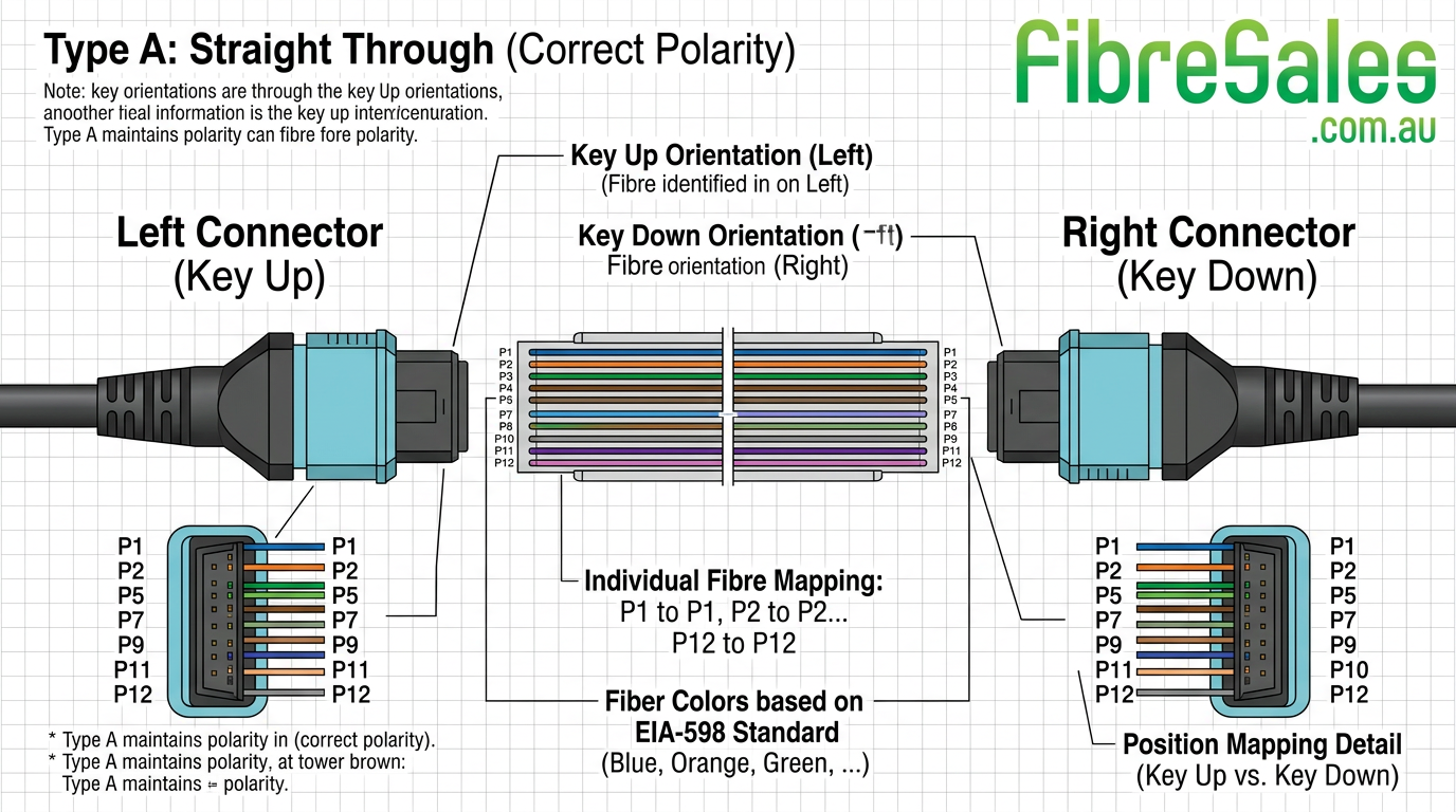
Type A (Straight Through Polarity)
Fibres maintain direct alignment from one end to the other.
Decision logic:
Used when structured end-to-end consistency is required across pre-terminated systems.
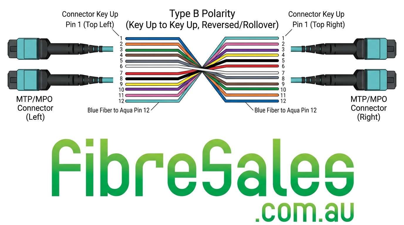
Type B (Reverse Polarity)
Fibres are reversed end-to-end to maintain correct transmit/receive pairing.
Decision logic:
Common in data centre backbone applications where parallel optics require mirrored alignment.
Polarity B
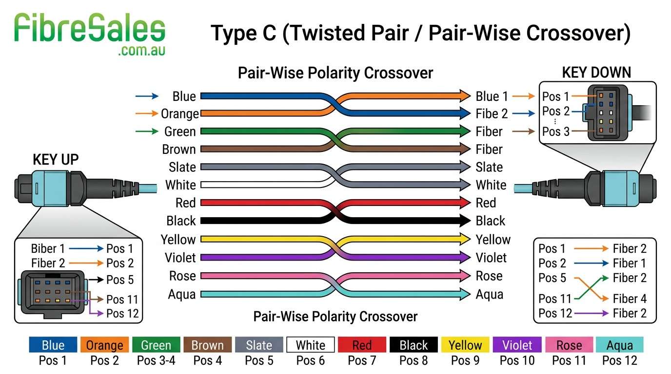
Type C (Pairwise Flip Polarity)
Adjacent fibre pairs are swapped within the connector.
Decision logic:
Used in controlled patching environments but requires strict documentation to avoid mismatches.
Fibre MPO Polarity Explained: Common Failure Scenarios
Most polarity issues occur during installation or patching rather than manufacturing defects.
Typical failure causes:
- incorrect cassette selection
- mixed polarity types in same link
- undocumented patch lead changes
- incorrect trunk orientation
Decision logic:
If a link fails after patching but worked previously, polarity mismatch is more likely than hardware failure.
Fibre MPO Polarity Troubleshooting Guide
A structured approach is required to isolate polarity issues.
Step-by-step process:
- verify fibre continuity
- test individual channel mapping
- inspect cassette polarity type
- confirm trunk orientation
- validate patch lead configuration
- retest full link
Fibre MPO Polarity Explained: Installation Best Practices
Correct polarity management is primarily a design discipline, not a testing correction step.
Best practices:
- standardise polarity type across infrastructure
- clearly label all MPO trunks and cassettes
- avoid mixing polarity methods in same rack row
- document every patch change
Decision logic:
If polarity is not standardised at design stage, troubleshooting becomes significantly more complex during scaling or fault isolation.
Fibre MPO Polarity vs Duplex Fibre Systems
Unlike duplex LC systems:
- MPO carries multiple fibre channels simultaneously
- polarity errors affect entire multi-lane links
- troubleshooting requires mapping rather than simple continuity testing
Decision logic:
If duplex systems work but MPO systems fail in the same environment, polarity configuration is the most likely cause.
Engineering Decision Insight
MPO polarity issues are rarely hardware faults. They are almost always:
- documentation issues
- installation inconsistencies
- patching errors
Technicians prioritise mapping verification over component replacement because physical fibre failure is statistically less likely.