Fibre Distance Calculator Guide showing Network Distance Limits
INTRODUCTION
Fibre optic distance limits are determined by more than just cable length. Real-world fibre network performance depends on attenuation, transceiver power, connector quality, wavelength, and overall system design.
Many fibre links fail not because the cable is damaged, but because the network exceeds the optical limitations of the system.
This Fibre Distance Calculator Guide explains how fibre distance is calculated, what affects transmission range, and how engineers determine whether a fibre link will operate reliably.
For fibre optic cabling, SFP modules, patch leads, and testing equipment, visit www.fibresales.com.au.
Fibre Distance Calculator Guide: What Determines Fibre Distance Limits
Fibre distance is controlled by the total optical loss and signal integrity across the link.
FOA Fibre Optic Distance Fundamentals
The major factors affecting distance include:
- fibre type
- wavelength
- attenuation
- dispersion
- connector loss
- splice quality
- transceiver output power
Decision logic:
If a fibre link exceeds its designed distance, attenuation and dispersion should be investigated before replacing hardware.
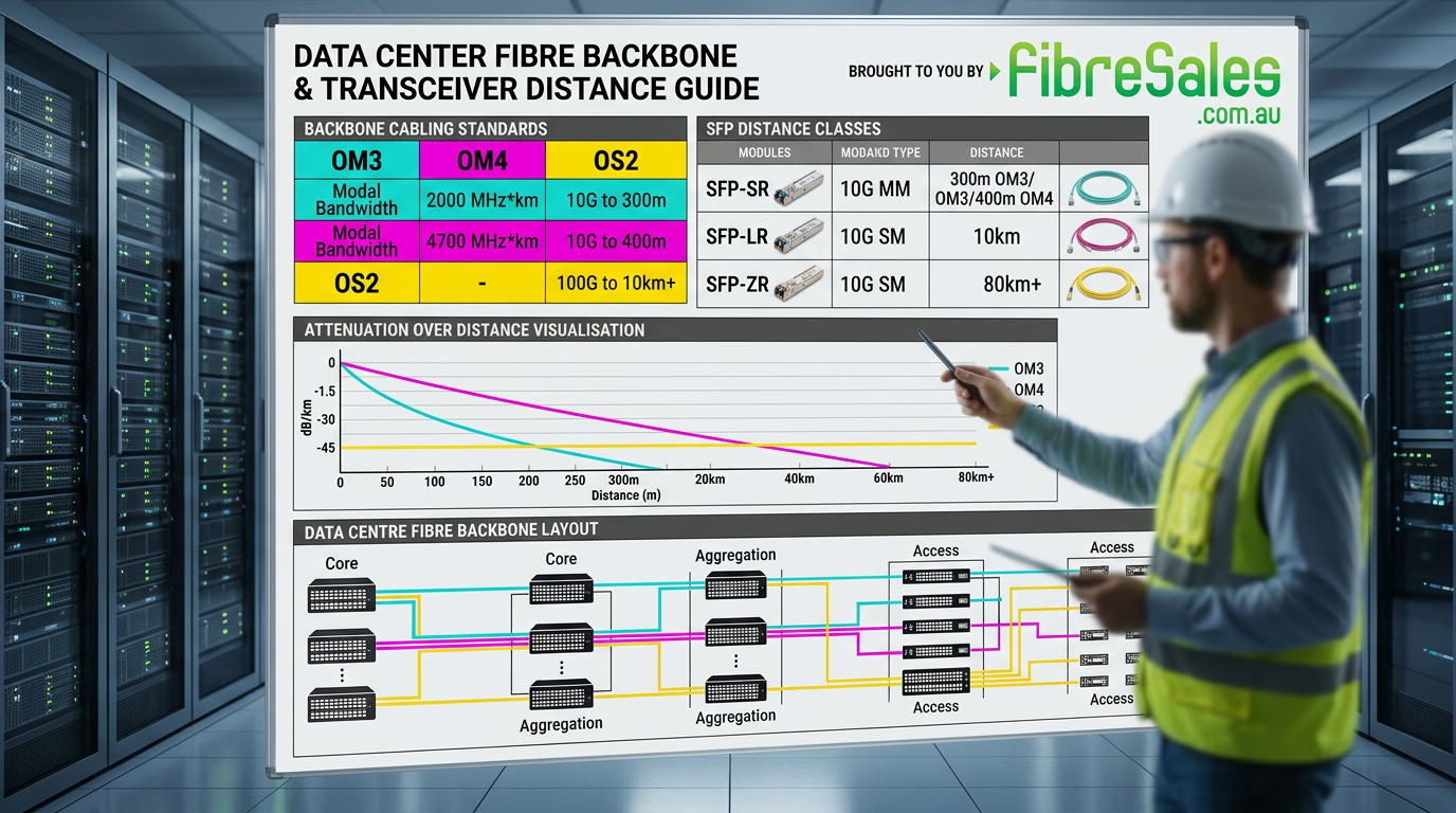
Fibre Distance Calculator Guide: Singlemode vs Multimode Distance
Different fibre types support different transmission distances.
Singlemode Fibre (OS2)
Singlemode fibre supports the longest transmission distances because light travels through a smaller core with reduced modal dispersion.
Typical applications include:
- long-distance backbone networks
- telecommunications infrastructure
- campus fibre links
- data centre interconnects
Multimode Fibre (OM3, OM4, OM5)
Commonly used for:
- short-range high-speed networking
- server connectivity
- structured cabling systems
Distance capability depends heavily on:
- fibre grade
- transceiver type
- network speed
Decision logic:
If network distance requirements exceed multimode limitations, singlemode fibre is usually the more reliable long-term solution.
Fibre Distance Calculator Guide: OM3 vs OM4 Distance Limits
Widely used in modern data centres.
Typical distance examples include:
| Network Speed | OM3 Distance | OM4 Distance |
|---|---|---|
| 10G | 300m | 400m |
| 40G | 100m | 150m |
| 100G | 70m | 100m |
Cisco Fibre Distance Reference
Decision logic:
If upgrading network speed while keeping existing multimode fibre, distance limits should always be validated before deployment.
Fibre Distance Calculator Guide: SFP Module Distance Ratings
SFP and QSFP modules are designed for specific transmission distances.
Common examples include:
- SR = short range
- LR = long range
- ER = extended range
- ZR = ultra-long range
Distance capability depends on:
- wavelength
- optical power
- receiver sensitivity
- fibre type
Decision logic:
If incompatible SFP modules are installed, link instability may occur even if the fibre itself tests correctly.
Fibre Distance Calculator Guide: Real-World Fibre Loss Factors
Actual field performance is rarely identical to theoretical calculations.
Common causes of additional loss include:
- dirty connectors
- poor splices
- excessive bend radius
- patch panel losses
- incompatible optics
- ageing infrastructure
IEEE Optical Network Standards Overview
Decision logic:
If measured distance performance differs significantly from specifications, accumulated connector and patching losses are often responsible.
Fibre Distance Calculator Guide: How Engineers Calculate Distance
Engineers calculate fibre distance using:
- attenuation calculations
- optical power budgets
- wavelength specifications
- transceiver tolerances
- system safety margins
This connects directly to:
https://fibresales.com.au/fibre-optic-power-budget-calculator-guide-understanding-link-loss-and-system-limits/
Decision logic:
If safety margin is ignored during design, links may initially work but become unstable as contamination and ageing increase attenuation.
Common Distance Calculation Mistakes
The most common design mistakes include:
- ignoring connector losses
- mixing incompatible fibre types
- incorrect wavelength selection
- underestimating patch panel loss
- exceeding multimode bandwidth limitations
Decision logic:
If intermittent fibre faults occur only under high traffic loads, bandwidth limitations or marginal power budget are often contributing factors.
Fibre Distance Calculator Guide: Distance vs Network Speed
Higher network speeds generally reduce maximum transmission distance.
This occurs because:
- signal integrity requirements increase
- dispersion becomes more significant
- power margin decreases
Examples:
- 1G networks tolerate greater distances
- 10G introduces tighter loss requirements
- 40G and 100G demand precise infrastructure quality
Decision logic:
If upgrading network speed causes failures on existing fibre, infrastructure limitations should be evaluated before replacing switches.
Engineering Decision Insight
Distance limitations are rarely caused by cable length alone. Engineers evaluate the entire optical system including:
- fibre type
- connector quality
- optical power budget
- transceiver compatibility
- patching infrastructure
Technicians prioritise validating optical performance before assuming hardware failure.