Understanding Fibre Optic Attenuators
Fibre optic attenuators play a crucial role in optical networks by maintaining optimal signal power levels. These passive devices function without an external power source, making them reliable and efficient. In fibre optic communication systems, excessive signal strength can overwhelm and damage receivers. Attenuators prevent this by reducing optical signal power to safe levels.
Categories of Optical Attenuators
Optical attenuation fall into two main categories:
- Fixed Optical Attenuation (FOA) – These attenuators have a predetermined attenuation level and work best in stable network environments.
- Variable Optical Attenuation (VOA) – These allow dynamic adjustments to attenuation levels, making them ideal for testing and monitoring.
Additionally, attenuators are classified based on the type of fibre optic cable they support:
- Single-mode attenuation – Used in long-distance, high-power applications where laser sources generate intense signals.
- Multimode attenuation – Less common, as multimode light sources such as LEDs and VCSELs typically do not produce excessive power.
This article focuses exclusively on Fixed Optical Attenuators (FOAs) and their role in optical networks.

What is a Fixed Fibre Optic Attenuator?
A Fixed Fibre Optic Attenuator reduces optical signal power by a fixed amount. Network engineers use these devices to prevent signal distortion and receiver overload, ensuring smooth data transmission.
How Do Optical Attenuators Work?
A Fixed optical attenuator absorb, reflect, scatter, or disperse light to reduce signal intensity while minimizing loss or distortion.
A simple analogy for their function is sunglasses. Just as sunglasses filter excessive sunlight to protect the eyes, fibre optic attenuators regulate optical power to keep receivers within safe operating limits.
Types of Fixed Optical Attenuators
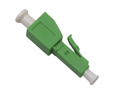
Manufacturers produce fixed attenuators in various designs to suit different applications. The most common type is the male-to-female adaptor style attenuator, which fits between a fibre optic cable and the receiving equipment or patch panel. These attenuators match specific connector types, including:
- 2.5mm FC, ST, SC connectors
- 1.25mm LC connectors
How Manufacturers Design Fixed Optical Attenuators
A fixed attenuator achieves controlled signal reduction through several design techniques:

- Gap-loss method – Introduces a small gap between fibre cores to reduce signal strength.
- Angular or lateral misalignment – Purposefully misaligns fibre cores to lower power.
- High-loss fusion splicing – Uses a specific splicing technique to introduce controlled loss.
- Density filters – Absorb specific light wavelengths to reduce signal intensity.
- Stress-based attenuation – Applies pressure to the fibre to create controlled signal loss.
They maintain a constant attenuation level, typically ranging from 1dB to 20dB. Standard values include 1dB, 2dB, 3dB, 5dB, 10dB, 15dB, and 20dB, though manufacturers can produce custom levels to meet specific network requirements.

Applications of Fixed Optical Attenuators
Network engineers rely on fixed fibre optic attenuators in telecommunications, data centers, and laboratory environments. Common applications include:
- Preventing receiver saturation – Strong optical signals can overload and damage receivers. Attenuators regulate power levels to prevent this.
- Balancing power in Wavelength Division Multiplexing (WDM) systems – Attenuators ensure uniform power distribution across all channels.
- Testing and troubleshooting – Engineers use attenuators in bit error rate (BER) testing to analyze system performance under different power levels.
- Stress testing – Gradually reducing signal power helps determine a fibre optic link’s safety margin before failure.

How to Calculate the Required Attenuation Level
Selecting the correct attenuation level ensures optimal network performance. Engineers determine this through loss budgeting, which involves two key calculations:
- Power budget – The maximum allowable signal loss between the transmitter and receiver.
- Loss budget – The expected total loss in a cable system based on installed components.
Example Calculation:
Given the following network parameters:
- Transmitter power (TP) = 3dBm
- Maximum receiver input power (MP) = -6dBm
- Total fibre and connection loss (TL) = 2dB
The required minimum attenuation is:
Minimum attenuation = MP + TL – TP
= (-6 dBm) + (2 dB) – (3 dBm)
= -5 dB
To prevent receiver overload, the system needs at least a 5dB attenuator. Using a higher-value attenuator is possible, but excessive attenuation can weaken the signal too much.

Conclusion
Fixed optical attenuators play a vital role in maintaining the efficiency and longevity of fibre optic networks. Whether permanently integrated into network infrastructure or temporarily used for testing, these devices regulate power levels to ensure stable operation.
With attenuation values ranging from 1dB to 20dB, engineers can fine-tune networks for optimal performance. Understanding how fixed fibre optic attenuators work enables network technicians to optimize signal strength, protect equipment, and ensure reliable data transmission. Their essential role makes them a staple in every fibre optic technician’s toolkit.