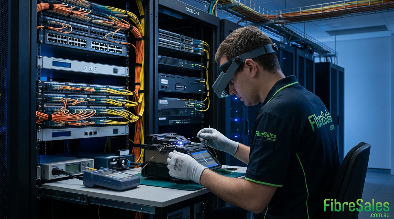
Fibre optic splicing joins two optical fibres to create a continuous, low-loss optical path. Although the principle is straightforward, achieving a reliable splice requires accurate fibre preparation, precision cleaving, correct alignment, contamination control and appropriate protection of the completed joint.
Professional fibre optic splicing supports telecommunications networks, data centres, industrial infrastructure, mining networks, backbone cabling and fibre repair projects.
Two primary methods are used: fusion splicing and mechanical splicing. Both join optical fibres, although they achieve that connection differently. Fusion splicing permanently joins prepared fibre ends using a controlled electric arc, while mechanical splicing precisely aligns the fibres inside a mechanical fixture.
For permanent network infrastructure, technicians generally prefer fusion splicing because it can produce a low-loss, mechanically stable connection.
fibreSales supplies professional fusion splicers, fibre pigtails, fibre enclosures and associated installation products for fibre technicians, contractors and network installers.
What Is Fibre Optic Splicing?
Fibre optic splicing is the process of joining the glass cores of two optical fibres so that light can travel from one fibre into the other with minimal disruption.
Unlike a connectorised interface that technicians can disconnect and reconnect, a fibre splice generally becomes part of the permanent optical link.
Network installations commonly require splicing when
- joining fibre cable sections during network construction
- connecting backbone fibres to pigtails inside an enclosure
- extending an existing fibre route
- repairing damaged fibre cable
- restoring a failed network link
- transitioning between cable sections
- terminating backbone fibre into patching infrastructure
The objective is not simply to make the two fibres touch. Instead, the splice must maintain accurate core alignment while minimising insertion loss, reflection and long-term mechanical risk.
For this reason, the quality of the preparation before the actual splice is often just as important as the fusion process itself.
Why Fibre Optic Splicing Quality Matters
Every splice becomes an optical event within the completed fibre link. Poor workmanship can therefore introduce additional loss or create a weak point that causes problems later.
Several factors influence splice quality, including:
- fibre cleanliness
- stripping technique
- cleave angle and end-face quality
- fibre type compatibility
- core alignment
- fusion-splicer configuration
- electrode condition
- environmental conditions
- correct placement of the splice protection sleeve
A splice that appears successful during installation is not automatically a good splice. Consequently, technicians should assess the splice result and subsequently verify the completed link using appropriate fibre-testing methods.
For permanent backbone infrastructure, even small improvements in individual splice quality become increasingly important when a route contains numerous splices. Optical losses accumulate throughout the link and contribute to the overall system power budget.
Engineering Decision
A successful fibre splice should be treated as an optical and mechanical connection, not merely a joining operation.
If the installation is permanent, difficult to access or carrying business-critical traffic, prioritise low splice loss, repeatability, mechanical protection and testability rather than installation speed alone.
Fusion Splicing vs Mechanical Splicing
The two principal methods of fibre optic splicing solve the same basic problem in different ways.
| Factor | Fusion Splicing | Mechanical Splicing |
|---|---|---|
| Joining method | Fibre ends are permanently fused | Fibre ends are mechanically aligned |
| Equipment | Fusion splicer and precision cleaver | Mechanical splice fixture and cleaver |
| Typical role | Permanent network infrastructure | Repairs and selected field applications |
| Connection | Permanent | Mechanically retained |
| Repeatability | High with correct preparation and equipment | More dependent on preparation and fixture |
| Long-term application | Preferred for permanent infrastructure | More application-specific |
| Fibre preparation | Strip, clean and precision cleave | Strip, clean and precision cleave |
Fusion splicing uses precision motors and an electric arc to align and fuse prepared fibres. Modern fusion splicers can also inspect the cleaved fibre ends, align the fibres and estimate splice loss before the completed splice is protected.
Mechanical splicing does not melt the fibres together. Instead, prepared fibre ends are aligned within a purpose-designed fixture, often using an index-matching material to reduce optical discontinuity at the joint.
Neither method eliminates the need for accurate preparation. A poor cleave, contaminated fibre or damaged glass can compromise either type of splice.
For a detailed engineering and commercial comparison, including cost, loss and reliability considerations, see Fusion Splicing vs Mechanical Splicing: Cost, Loss & Reliability Compared.
How Fusion Splicing Works
Fusion splicing creates a permanent joint by precisely aligning two prepared optical fibres and fusing their glass ends together with a controlled electric arc.
However, the actual fusion is only one stage of the procedure. Reliable results depend on a sequence of preparation, inspection, alignment, fusion, protection and verification.
1. Prepare the Fibre
Before splicing begins, expose sufficient working fibre and organise it so that it can be handled without introducing excessive bending or mechanical stress.
The technician should also confirm that the fibres being joined are appropriate for the intended splice and that the correct splice program or fibre type is selected on the fusion splicer.
Before progressing further, place the required splice protection sleeve over one of the fibres.
This seemingly minor step matters. Once the fibres have been fused, the sleeve cannot simply be placed over the completed splice without breaking the fibre and starting the preparation process again.
2. Strip and Clean the Fibre
Remove the required length of coating using the appropriate fibre stripping tool. The exposed glass must then be cleaned carefully to remove coating residue and contamination.
Avoid touching the prepared bare fibre.
Contamination introduced at this stage can interfere with cleaving, alignment and fusion quality. Therefore, cleanliness should take priority over speed.
3. Precision Cleave the Fibre
The cleave is one of the most important stages in fibre optic splicing.
A precision fibre cleaver produces a controlled, near-perpendicular end face so that the two fibres can be accurately aligned and fused.
Poor cleaves can cause:
- excessive splice loss
- failed fusion attempts
- poor fibre alignment
- weak or inconsistent joints
- unnecessary rework
The old assumption that a fusion splicer can compensate for any fibre preparation problem is incorrect. The machine can assist with inspection and alignment, but the quality of the prepared fibre still establishes the conditions for a successful splice.
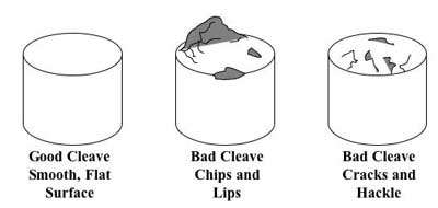
The quality of the fibre end affects signal loss. Simply placing broken fibre ends together without proper cutting would cause issues. A cleave tool ensures fibres have smooth, flat ends. Most cleave tools include a bin for collecting broken fibre ends safely.
Loading the Fibres into the Fusion Splicer
Once both fibres have been stripped, cleaned and correctly cleaved, they can be loaded into the fusion splicer.
Correct positioning is essential. The prepared fibre ends must sit securely in the machine without contamination, excessive movement or interference with the alignment process.
A typical loading sequence is:
- Open the wind protector.
- Open the left and right fibre clamps.
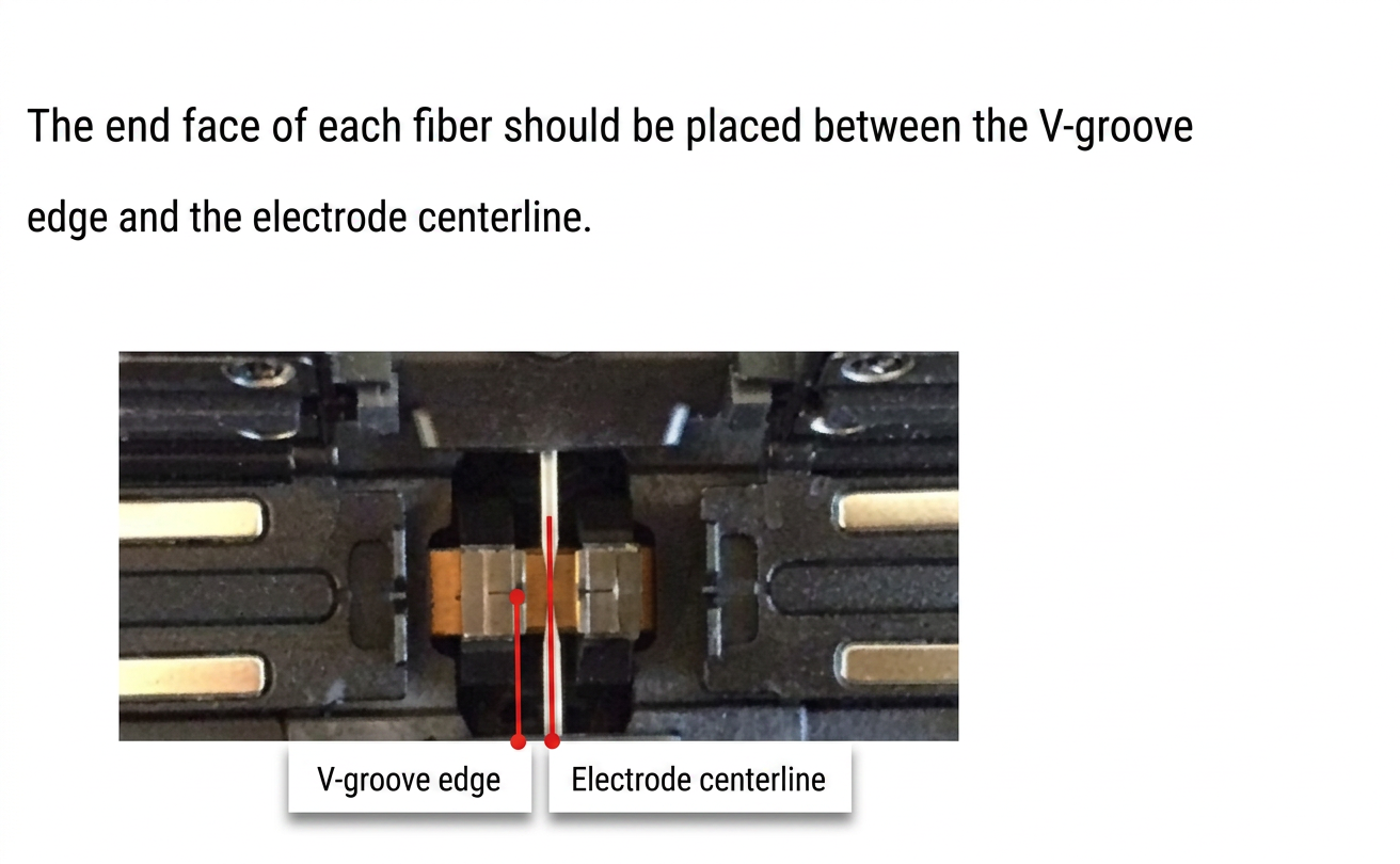
- Position the first prepared fibre correctly in the V-groove.
- Ensure the cleaved end is positioned within the splicer’s specified loading range.
- Close the fibre clamp carefully without disturbing the prepared end.
- Repeat the process for the second fibre.
- Confirm that neither fibre has moved or picked up contamination.
- Close the wind protector.
Do not allow the freshly cleaved fibre ends to contact fingers, work surfaces, tools or other contaminated objects. If contamination is suspected, prepare the fibre again rather than relying on the fusion process to compensate for it.
The original article refers to setting the cleaver length according to whether a 40 mm or 65 mm heat-shrink protection sleeve is being used. That remains useful field advice; however, technicians should follow the requirements of the particular fusion splicer, cleaver and protection sleeve rather than assuming one preparation length applies universally.
Fibre Alignment and Cleave Inspection
Modern fusion splicers use cameras and precision positioning systems to inspect and align the prepared fibres before fusion.
Depending on the machine and selected operating mode, the splicer may identify problems such as:
- unacceptable cleave angles
- contaminated fibre ends
- incorrect fibre positioning
- alignment problems
- fibre preparation defects
This is an important advantage during field work because a defective fibre end can often be identified before the fibres are permanently joined.
However, an automated inspection does not remove the need for good preparation. If the machine identifies a poor cleave or contaminated fibre, the correct response is generally to remove the affected fibre and prepare it again.
Completing the Fusion Splice
Once the fibres are correctly positioned and the fusion splicer has accepted the cleave and alignment, the actual fusion cycle can begin.
In automatic operating modes, the splicer typically controls the alignment and fusion sequence after the wind protector is closed. Precision motors position the fibres, while the electrodes generate a controlled electric arc that softens the glass and joins the fibre ends.
During this process, the technician should watch the splicer display rather than assuming that every completed cycle represents an acceptable splice.
The machine may provide an estimated splice loss after fusion. This estimate is useful as an immediate quality indicator; however, it should not be treated as a substitute for testing the completed optical link.
Check the Splice Before Removing It
Before removing the newly fused fibre, inspect the displayed splice image and any information provided by the fusion splicer.
Look for indications of:
- abnormal fibre alignment
- bubbles or visible defects
- excessive estimated splice loss
- an irregular splice profile
- warnings generated by the splicer
- movement or separation of the fibres
If the splice result is unacceptable, it is generally better to cut out the defective splice and repeat the preparation process than to leave a questionable joint inside the network.
This is especially important for backbone links and installations where the splice enclosure may become difficult or expensive to access after commissioning.
Perform the Appropriate Proof or Tension Test
Many fusion splicers can perform a controlled proof or tension test after the fusion cycle.
This test applies a small controlled force to the completed splice to help identify an obviously weak joint before it is protected and installed in the enclosure.
Where supported by the equipment and appropriate for the fibre and project requirements, use the manufacturer’s recommended proof-test settings rather than applying uncontrolled manual force to the fibre.
A splice that fails at this stage should be remade.
Finding a weak splice while the technician still has the fibres on the workbench is considerably better than discovering it after the cable has been dressed into an enclosure and commissioned.
Protecting the Completed Fibre Splice
A successful fusion joint still consists of exposed glass and requires mechanical protection before it can be safely stored.
This is the purpose of the splice protection sleeve fitted to the fibre before the splice began.
Once the fusion and appropriate checks are complete:
- Open the wind protector.
- Release the fibre clamps carefully.
- Remove the fused fibre without placing unnecessary stress on the joint.
- Slide the previously installed protection sleeve over the splice.
- Centre the splice correctly inside the sleeve.
- Place the protected section into the fusion splicer’s heater.
- Close the heater cover.
- Start the heating cycle.
- Allow the complete heating cycle to finish.
- Remove the protected splice carefully and allow it to cool before handling or storing it.
The sleeve reinforces the vulnerable stripped section and helps protect the completed splice from bending and mechanical damage.
However, the sleeve does not make the splice indestructible. Technicians should still handle the protected fibre carefully when routing it into the splice tray.
Store the Splice Correctly
After cooling, place the protected splice into the designated holder within the splice tray or fibre enclosure.
Route the remaining fibre neatly through the tray while maintaining the appropriate bend radius and avoiding unnecessary crossing, twisting or pressure.
For installations involving backbone cables and pigtail termination, fibreSales supplies fibre pigtails and fibre enclosures for organised fibre termination and splice management.
Good splice management matters because a technically successful fusion splice can still become a network problem if the fibre is subsequently pinched, sharply bent or poorly stored inside the enclosure.
Mechanical Fibre Splicing
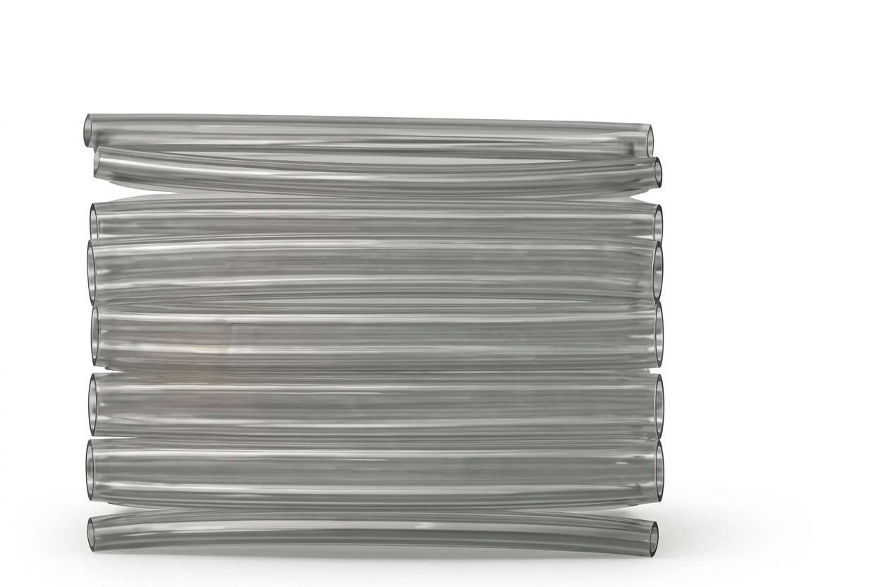
Mechanical splicing joins two prepared optical fibres without permanently fusing the glass together. Instead, the stripped and cleaved fibre ends are precisely aligned and retained inside a mechanical splice assembly.
Many mechanical splices use an index-matching material between the fibre ends to reduce reflections and optical loss at the joint.
The preparation stages remain critical. Each fibre must be:
- correctly stripped
- thoroughly cleaned
- precision cleaved
- positioned accurately inside the mechanical splice
- secured according to the splice manufacturer’s instructions
Unlike fusion splicing, the fibres remain separate physical components inside the mechanical assembly.
When Is Mechanical Splicing Useful?
Mechanical splicing can be appropriate when:
- a rapid field repair is required
- fusion-splicing equipment is unavailable
- the connection is temporary
- only a small number of fibres require joining
- the particular installation does not justify a fusion-splicing setup
However, installation speed or equipment cost should not be considered in isolation. Optical performance, reliability, accessibility and the expected service life of the network should also influence the decision.
For permanent backbone infrastructure and other performance-critical networks, fusion splicing is generally the preferred approach because it creates a permanent glass-to-glass joint.
For a deeper comparison, including cost and reliability considerations, see Fusion Splicing vs Mechanical Splicing: Cost, Loss & Reliability Compared.
Why Fibre Cleaving Is Critical to Splice Quality
Regardless of the splicing method, the condition of the fibre end has a major influence on the final result.
A fibre cleaver is designed to produce a controlled end face suitable for alignment and splicing. Simply breaking or cutting optical fibre with an inappropriate tool does not produce the precision required for reliable optical performance.
Poor cleaving can result in:
- excessive splice loss
- inconsistent alignment
- rejected fusion cycles
- increased rework
- mechanically weak splices
- unreliable mechanical-splice performance
Therefore, technicians should inspect and maintain their cleaver rather than assuming that every cleave produced by the tool is acceptable.
A worn, contaminated or damaged cleaver blade can repeatedly produce poor fibre ends. If splice quality suddenly deteriorates across multiple fibres, the cleaver should be one of the first parts of the preparation process investigated.
Cleaved fibre fragments also require careful handling. Bare glass fragments can be extremely small and difficult to see, so technicians should collect and dispose of them using an appropriate fibre-shard container rather than leaving fragments on the work surface.
Fibre Optic Splicing Tools and Equipment
Professional fibre optic splicing requires more than the fusion splicer itself. The complete preparation and protection process relies on several specialised tools and consumables.
Typical equipment includes:
| Equipment | Primary purpose |
|---|---|
| Fusion splicer | Aligns and permanently fuses prepared fibres |
| Precision fibre cleaver | Produces a splice-ready fibre end face |
| Fibre stripper | Removes the fibre coating without damaging the glass |
| Fibre cleaning materials | Remove contamination and coating residue |
| Splice protection sleeves | Mechanically protect completed fusion splices |
| Fibre pigtails | Provide connectorised termination from spliced backbone fibres |
| Splice tray/enclosure | Protects and organises completed splices |
| Fibre test equipment | Verifies optical performance after installation |
The quality of the supporting tools matters. An advanced fusion splicer cannot consistently compensate for poor stripping, contaminated fibre or an unreliable cleaver.
For technicians establishing or upgrading their splicing capability, fibreSales supplies professional fusion splicers, fibre installation equipment and associated termination products.
Technicians carrying out broader termination work can also review Termination Kits Benefits to understand where complete tool kits can simplify field preparation and termination tasks.
Engineering Decision: Equipment Should Match the Work
Do not select a fusion splicer solely on purchase price.
Consider:
- fibre types being installed
- expected splice volume
- required alignment capability
- battery operation for field work
- environmental conditions
- cleave inspection capability
- heater and protection-sleeve workflow
- availability of consumables and support
- technician experience
- required test and documentation standards
For occasional repair work, equipment requirements may differ considerably from those of a contractor completing hundreds of backbone splices.
Fibre Pigtail Splicing and Enclosure Termination
One of the most common applications for fusion splicing is connecting backbone fibres to fibre pigtails.
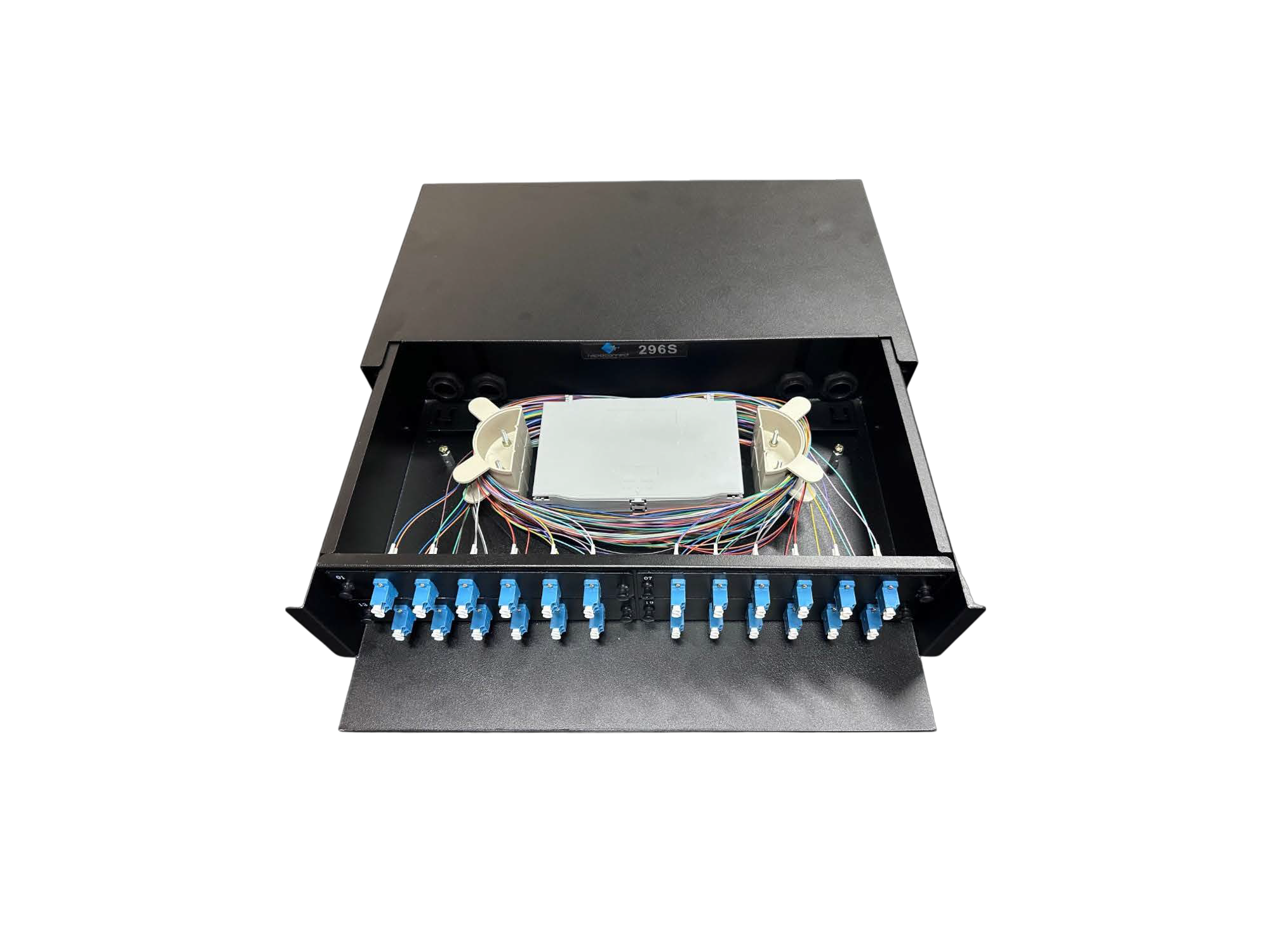
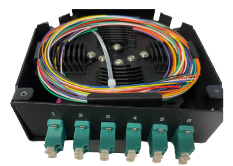
A pigtail provides a factory-terminated connector at one end and an unterminated fibre at the other. The unterminated end is spliced to the incoming backbone fibre, while the connectorised end interfaces with the patching equipment.
A typical workflow is:
Backbone fibre → fusion splice → pigtail → adaptor/patch panel → patch lead
This approach combines a controlled splice with a factory-terminated connector and is widely used in telecommunications rooms, data centres and structured fibre infrastructure.
fibreSales supplies fibre pigtails and fibre enclosures for these applications.
The splice itself must also be stored correctly. Completed protection sleeves should sit securely within the splice tray, while the remaining fibre should be routed without excessive bending, compression or interference with adjacent fibres.
For a broader explanation of termination options rather than splicing alone, see Fibre Termination Methods Explained.
Typical Fibre Splice Loss and What Affects It
A good splice aims to introduce as little additional optical loss as practical. However, there is no single loss value that should be assumed acceptable for every fibre, network or project.
The resulting splice loss can be influenced by:
- fibre core alignment
- cleave quality
- contamination
- incompatible or mismatched fibres
- fusion parameters
- electrode condition
- splicer calibration
- fibre geometry
- environmental conditions
- preparation technique
This is why the old article’s simple statement that fusion-splice loss is approximately 0.02–0.1 dB should not be treated as a universal acceptance limit.
Project specifications, network design requirements and applicable test criteria should determine whether a completed splice is acceptable.
Furthermore, the loss estimate displayed by a fusion splicer is an estimate produced by the machine. It is useful for identifying suspicious results during installation, but it does not replace optical testing of the completed link.
Where multiple splices exist along a fibre route, their losses also contribute to the overall optical link budget. Consequently, splice performance should be considered alongside connector loss, fibre attenuation and other passive losses rather than evaluated in isolation.
For network design calculations, see the Fibre Optic Power Budget Calculator Guide.
Common Fibre Optic Splicing Mistakes
Even high-quality equipment cannot compensate for poor fibre preparation or handling. In practice, many unsuccessful splices can be traced back to a small number of repeatable errors.
Poor Fibre Cleaning
Contamination is one of the most common causes of inconsistent splicing results.
After stripping, residue can remain on the bare glass. Dust, oils and other contaminants may also be introduced through handling or an unsuitable work area.
Therefore, clean the prepared fibre using appropriate fibre-cleaning materials before cleaving and avoid touching the bare glass afterwards.
If contamination occurs after cleaning or cleaving, prepare the fibre again rather than attempting to continue with a questionable end face.
Poor or Inconsistent Cleaving
A fusion splicer may identify a poor cleave before fusion, but technicians should not rely solely on the machine to compensate for preparation problems.
Repeated poor cleaves can indicate:
- a worn cleaver blade
- incorrect blade position
- contamination within the cleaver
- incorrect fibre placement
- poor stripping technique
- damaged fibre
If several consecutive splices produce abnormal results, investigate the preparation process before repeatedly adjusting fusion parameters.
Forgetting the Splice Protection Sleeve
This is a simple but costly field mistake.
The protection sleeve must normally be placed over one of the fibres before the fibres are fused. If it is forgotten, the technician cannot simply slide the sleeve onto the completed continuous fibre afterwards.
The splice generally has to be removed and remade.
A useful working sequence is:
Sleeve → Strip → Clean → Cleave → Load → Splice → Protect
Following the same sequence consistently reduces avoidable rework.
Using Incorrect Splicer Settings
Fusion splicers may provide different programs for fibre types and operating conditions.
Selecting an inappropriate program can affect alignment or fusion performance. Therefore, confirm the fibre type and relevant splice mode before beginning production work.
Avoid changing advanced arc or calibration parameters simply to make an unacceptable splice appear successful. Repeated problems should trigger investigation of the fibre, preparation equipment, electrodes and machine condition.
Mishandling the Fibre After Fusion
A successful splice is still vulnerable until it has been protected.
Avoid pulling, sharply bending or unnecessarily handling the bare fused section while transferring it from the splicer to the protection-sleeve heater.
After heating, allow the sleeve to cool appropriately before routing it into the splice tray.
Poor Splice-Tray Management
Good fusion work can be undermined by poor enclosure management.
Common problems include:
- fibres routed below their appropriate bend radius
- protection sleeves not seated correctly
- excessive fibre crossing
- fibres trapped beneath enclosure components
- insufficient service loop
- unclear identification and labelling
For broader cable-management and installation practices, refer to Fibre Installation Best Practices rather than expanding those installation topics here.
Cleaning and Contamination Control During Fibre Splicing
Cleanliness is fundamental throughout the fibre optic splicing process because contaminants can affect both preparation and optical performance.
A practical workflow is to maintain a clean working area and separate dirty preparation tasks from clean fibre handling wherever possible.
Technicians should:
- clean stripped fibre before cleaving
- keep V-grooves and fibre holders clean
- maintain the cleaver according to its instructions
- keep cleaning materials protected from contamination
- avoid touching prepared bare fibre
- keep the fusion-splicer work area protected from dust
- dispose of fibre shards safely
- inspect and clean connector end faces separately when completing connectorised termination
Connector contamination is a related but distinct issue. Where a spliced pigtail terminates at an adaptor or patching interface, the connector end face should be inspected and cleaned using an appropriate process before connection.
fibreSales supplies professional fibre cleaning products and fibre inspection microscopes for fibre preparation, inspection and maintenance workflows.
How to Verify a Completed Fibre Splice
A fusion splicer’s estimated loss is useful during the splicing process, but final network acceptance should be based on appropriate testing of the installed link.
The required test method depends on what needs to be verified.
For example:
| Verification requirement | Appropriate approach |
|---|---|
| Basic continuity | Continuity/VFL testing where appropriate |
| End-to-end optical loss | Calibrated light source and optical power meter |
| Location and characterisation of splice events | OTDR |
| Connector condition | Fibre inspection microscope |
| Overall link performance | Testing specified for the installed system/project |
An OTDR can help locate and characterise events along a fibre route, including splices. Meanwhile, a calibrated optical power meter used with an appropriate light source can verify end-to-end insertion loss.
The testing method should therefore match the acceptance requirement rather than relying on one instrument for every measurement.
For the complete testing workflow, equipment selection and interpretation of results, use the Fibre Optic Testing Guide.
This is also where we correct the obsolete link in the old Splicing and Installation Guide. Do not use /fibre-optic-testing-performance-guide-australia/ in the rebuilt article.
Where Fibre Optic Splicing Is Used
Fibre optic splicing is used wherever permanent or highly reliable fibre connections are required.
Common applications include:
Telecommunications Networks
Long fibre routes may require cables to be joined at planned splice locations. Fusion splicing provides a permanent connection while allowing fibres to be organised and protected within suitable closures or enclosures.
Data Centres
Splicing is commonly used when backbone fibres are terminated to pigtails inside fibre enclosures or patching infrastructure.
Because data-centre environments can contain large fibre counts, repeatable preparation, identification and splice management become particularly important.
Industrial and Mining Networks
Industrial fibre networks may operate across long distances or in environments where electromagnetic interference makes optical fibre particularly valuable.
The broader cable selection and physical protection requirements are separate installation decisions. For harsh environments where cable construction is the primary concern, see the Armoured Fibre Cable Guide.
Fibre Network Repairs
Damaged fibre routes may require sections to be exposed, prepared and respliced.
In these situations, technicians need to consider more than the immediate break. They should determine whether sufficient service length remains, whether the surrounding fibre has also been damaged and whether the repair can be stored and protected correctly.
Backbone and Pigtail Termination
Fusion splicing backbone fibres to connectorised pigtails provides a practical method of bringing permanent cabling into patching infrastructure.
This allows the permanent cable to remain protected while patch leads provide the accessible connection between equipment and the installed fibre system.
Engineering Decision: When Should You Fusion Splice?
Fusion splicing is generally the stronger choice when the connection will form part of permanent infrastructure and low loss, repeatability and long-term stability are priorities.
Consider fusion splicing when:
- the link is permanent
- multiple fibres require joining
- splice locations will become difficult to access
- the network carries critical services
- low and predictable splice loss is important
- backbone cable is being terminated through pigtails
- long-term reliability outweighs the initial equipment cost
Mechanical splicing may remain appropriate for selected repairs, low-volume work or circumstances where fusion equipment is unavailable.
However, the decision should consider whole-of-life network requirements, not simply which method is fastest at the moment of installation.
For projects involving regular fibre construction or maintenance, investing in appropriate fusion-splicing equipment can improve consistency and reduce dependence on temporary joining methods.
Real-World Fibre Splicing Example
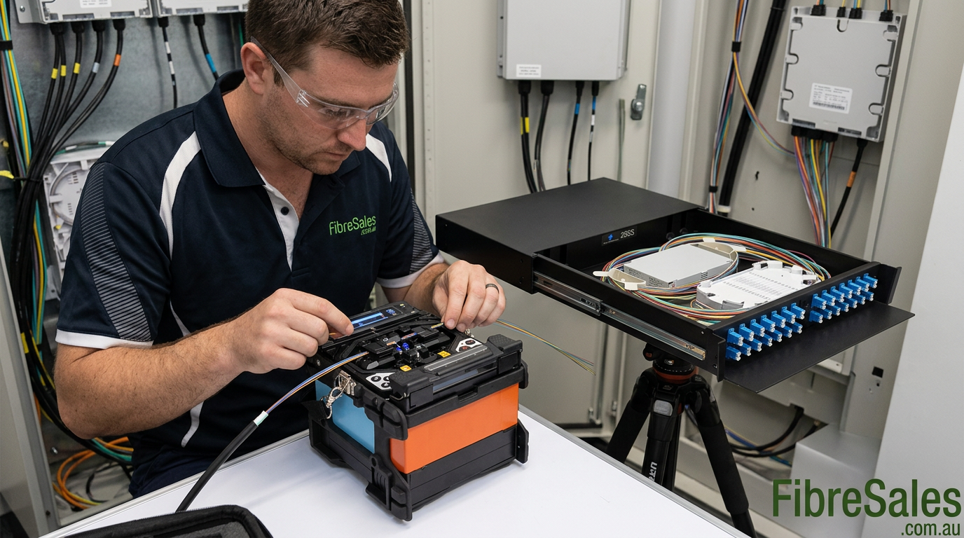
Consider a backbone fibre cable entering a communications enclosure where its fibres need to be presented as connectorised ports.
Rather than attempting to install connectors directly onto every backbone fibre, the technician can splice each required fibre to a factory-terminated pigtail.
The workflow is:
- prepare and organise the incoming backbone cable
- identify the required fibres
- place a protection sleeve onto each fibre before splicing
- strip and clean the fibre
- precision cleave the backbone fibre and pigtail
- load both fibres into the fusion splicer
- complete and assess the fusion splice
- protect the splice using the heat-shrink sleeve
- route the cooled splice into the splice tray
- connect the pigtail to the appropriate adaptor position
- inspect and clean connector interfaces
- test the completed fibre link
This approach separates the permanent backbone connection from routine patching while keeping the splice protected within the enclosure.
More importantly, each stage can be checked before the enclosure is closed. Problems with preparation, splicing, connector cleanliness or optical performance can therefore be corrected while the technician still has direct access to the installation.
Fibre Optic Splicing Standards and Best Practice
Professional fibre optic splicing should follow the requirements of the installed cabling system, project specification, equipment manufacturer and applicable industry standards.
Standards do not simply define whether two fibres can be joined. They help establish consistent expectations for installation quality, optical performance, testing, documentation and long-term reliability.
Relevant standards and industry guidance may include:
- ISO/IEC 11801 for generic customer-premises cabling
- applicable IEC fibre optic interconnecting device and passive component standards
- relevant TIA structured cabling requirements
- manufacturer requirements for the installed fibre and equipment
- project-specific optical-loss and acceptance criteria
- applicable Australian cabling requirements
In Australia, installers should also consider applicable regulatory requirements and project specifications. The Australian Communications and Media Authority provides information about Australian cabling standards and regulatory requirements.
For broader structured-cabling design and installation guidance, technicians can also refer to BICSI telecommunications distribution guidance.
Most importantly, technicians should not adopt a single splice-loss number as a universal pass/fail limit. Acceptance criteria should come from the relevant system design, project specification and test requirements.
Fibre Optic Splicing Best Practices
A repeatable workflow produces more reliable results than attempting to correct problems after the splice has been completed.
Before beginning a splicing job:
- confirm the fibre type and cable identification
- verify the required splice method
- inspect the fusion splicer and cleaver
- check that suitable protection sleeves and consumables are available
- establish a clean and stable work area
- confirm the correct splicer program
- prepare an appropriate fibre-shard disposal container
- understand the project’s testing and acceptance requirements
During splicing:
- place the protection sleeve on the fibre before fusion
- strip fibre carefully without damaging the glass
- clean before cleaving
- avoid touching prepared fibre
- reject questionable cleaves
- keep V-grooves and fibre holders clean
- investigate repeated poor splice results rather than simply resplicing indefinitely
- protect each completed splice promptly
- maintain appropriate fibre routing within the splice tray
After splicing:
- inspect the completed enclosure
- confirm identification and labelling
- inspect and clean connector interfaces
- test the installed fibre using the required method
- record results where project documentation requires them
The principle is straightforward: prepare carefully, splice consistently, protect correctly and verify the finished link.
Frequently Asked Questions About Fibre Optic Splicing
What is fibre optic splicing?
Fibre optic splicing is the process of joining two optical fibres so that light can continue from one fibre into the other with minimal disruption. The two main methods are fusion splicing and mechanical splicing.
What is fusion splicing?
Fusion splicing uses a precision machine to align prepared optical fibres and permanently fuse their glass ends together using a controlled electric arc.
What is mechanical fibre splicing?
Mechanical splicing aligns and retains two prepared fibre ends inside a mechanical fixture rather than permanently fusing the glass.
Is fusion splicing better than mechanical splicing?
For permanent fibre infrastructure, fusion splicing is generally preferred because it provides a permanent, repeatable connection. However, mechanical splicing can remain useful for selected repairs and low-volume applications. See the dedicated Fusion Splicing vs Mechanical Splicing guide for a detailed comparison.
How much loss should a fibre splice have?
There is no single splice-loss value that should be applied universally. Fibre characteristics, preparation, equipment, network design and project acceptance requirements all influence the result.
A fusion splicer’s estimated loss can help identify questionable splices, but final acceptance should follow the project’s specified testing criteria.
Why is fibre cleaving important?
Cleaving produces the controlled fibre end face required for accurate alignment and splicing. A poor cleave can increase loss, cause the fusion splicer to reject the fibre or result in an inconsistent joint.
Do you need to clean fibre before fusion splicing?
Yes. Residue and contamination on stripped fibre can interfere with preparation and fusion quality. The fibre should be cleaned using appropriate materials before cleaving.
What tools are needed for fusion splicing?
A typical setup includes a fusion splicer, precision cleaver, fibre stripper, suitable cleaning materials, splice protection sleeves and safe fibre-shard disposal. Additional tools and test equipment depend on the installation.
Why do you put the splice protection sleeve on before splicing?
Once two fibres have been permanently fused, a closed protection sleeve cannot be passed over the continuous fibre. Therefore, the sleeve must be placed onto one fibre before completing the splice.
Can a fusion splicer test the finished fibre link?
No. A fusion splicer may inspect fibre preparation and provide an estimated loss for the splice, but this does not replace appropriate testing of the completed fibre link.
For complete testing procedures, see the Fibre Optic Testing Guide.
Can an OTDR test a fibre splice?
An OTDR can locate and characterise events along a fibre link, including splice events. However, the appropriate test method depends on what the technician needs to verify.
What causes high fibre splice loss?
Potential causes include contamination, poor cleaving, fibre misalignment, incompatible fibres, unsuitable fusion parameters, electrode condition and preparation problems.
Repeated high-loss results should trigger investigation of the complete preparation and splicing process rather than repeated attempts using the same conditions.
Where are fibre splices stored?
Protected splices are typically organised in splice trays within suitable fibre enclosures. The enclosure protects the fibres while maintaining orderly routing and appropriate bend control.
Can fibre pigtails be fusion spliced?
Yes. Fusion splicing backbone fibres to connectorised pigtails is a common termination method. fibreSales supplies fibre pigtails and fibre enclosures for these applications.
Should every completed fibre splice be tested?
The completed installation should be tested according to the project’s acceptance requirements. Testing may include end-to-end insertion-loss measurement, OTDR analysis or other specified verification.
Why Choose fibreSales for Fibre Optic Splicing Equipment?
Successful fibre optic splicing depends on the complete workflow rather than one piece of equipment.
fibreSales supports Australian fibre technicians, contractors and network installers with products for fibre preparation, splicing, termination, inspection and testing.
Depending on the project, this can include:
- fusion splicers
- fibre pigtails
- fibre enclosures
- fibre cleaning products
- fibre inspection microscopes
- OTDR equipment
- optical power meters
- optical light sources
Selecting compatible preparation, splicing and testing equipment helps technicians build a more consistent workflow from bare fibre preparation through to final network verification.
Conclusion
Fibre optic splicing is a precision process in which preparation quality matters just as much as the fusion itself. Reliable results depend on clean fibre, accurate cleaving, correct alignment, suitable splicer settings, proper splice protection and verification of the completed installation.
For permanent backbone infrastructure, fusion splicing is generally the preferred joining method. Mechanical splicing still has useful applications, particularly for selected repairs and situations where fusion equipment is unavailable.
However, whichever method is selected, the engineering objective remains the same: create a mechanically secure connection while introducing as little unnecessary optical loss as practical.
For professional fusion splicers, fibre preparation equipment, pigtails, enclosures, cleaning products and test equipment, visit www.fibresales.com.au for fibre optic solutions, technical resources and installation products.
Continue Learning
- Fusion Splicing vs Mechanical Splicing: Cost, Loss & Reliability Compared — compare the two joining methods in greater detail.
- Fibre Termination Methods Explained — understand splicing, connectorisation and other termination approaches.
- Fibre Installation Best Practices — continue into broader installation practices without duplicating them in this splicing guide.
- Fibre Optic Testing Guide — learn how completed fibre links are tested and verified.
- Fibre Optic Power Budget Calculator Guide — understand how splice, connector and fibre losses contribute to the overall optical budget.