SFP Transceivers Explained | Complete Guide to Choosing the Right SFP
SFP transceivers provide a compact, modular way to connect switches, routers, media converters and other compatible network equipment to fibre optic or copper links. Because network designers can select the transceiver separately from the host equipment, SFP-based ports provide considerably more flexibility than interfaces built for only one cable type or transmission distance.
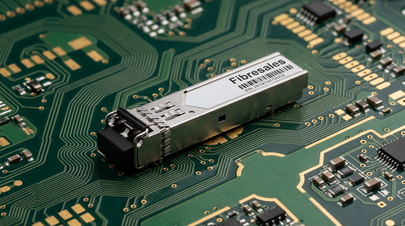
SFP stands for Small Form-factor Pluggable. These compact transceiver modules plug into compatible SFP ports and provide the physical interface between the host network equipment and the transmission medium.
Depending on the module and equipment, an SFP can support multimode fibre, singlemode fibre, bidirectional fibre or copper Ethernet connections. However, physical fit alone does not guarantee compatibility. Data rate, wavelength, fibre type, transmission distance, connector configuration and host-device requirements must all match the intended network.
Consequently, choosing an SFP transceiver should never come down to simply finding a module that fits the port.
For Gigabit Ethernet applications, fibreSales supplies 1.25G SFP transceivers, while higher-speed applications can use compatible 10G SFP+ transceivers.
What Is an SFP Transceiver?
An SFP transceiver is a compact, hot-pluggable module that fits into a compatible network-device port and provides the interface required for the selected communication medium.
In a fibre application, the module converts electrical signals from the host equipment into optical signals for transmission across the fibre. At the receiving end, another compatible transceiver detects the incoming optical signal and presents the corresponding electrical interface to its host equipment.
This modular design allows a network switch to support different link requirements without manufacturers having to build a dedicated optical interface permanently into every port.
For example, suitable SFP transceivers can allow compatible equipment to connect across:
- short multimode fibre links
- longer singlemode fibre links
- bidirectional single-fibre links
- copper Ethernet connections
- different optical wavelengths and reach requirements
This flexibility is one reason SFP transceivers remain widely used in enterprise networks, telecommunications infrastructure, data centres, industrial networks and fibre distribution systems.
What Does Mini-GBIC Mean?
You may also encounter the term mini-GBIC when discussing SFP modules.
GBIC stands for Gigabit Interface Converter. Earlier GBIC modules provided a removable transceiver interface but occupied considerably more physical space. The smaller SFP form factor allowed network manufacturers to increase port density while retaining the benefits of modular transceivers.
As a result, people sometimes use mini-GBIC as another name for an SFP. However, when selecting equipment, it is better to work from the actual port and transceiver specifications rather than relying on informal terminology.
How Do SFP Transceivers Work?
An optical SFP provides the transmit and receive functions required to move network data across an optical fibre link.
A conventional duplex optical SFP typically uses separate optical paths for transmission and reception:
- Tx sends the optical signal.
- Rx receives the optical signal.
The corresponding transceiver at the opposite end performs the complementary functions. Therefore, the transmit path at one end must reach the receive path at the other.
Inside an optical transceiver, the transmitter generates light at the module’s specified wavelength, while the receiver detects incoming optical signals within its operating requirements.
However, successful communication requires more than simply connecting two optical modules. The transceivers and fibre link must form a compatible system.
Important parameters can include:
- data rate
- operating wavelength
- fibre type
- supported transmission distance
- connector interface
- optical transmit power
- receiver sensitivity
- host-device compatibility
A mismatch in any critical parameter can prevent the link from establishing or produce unreliable network performance.
How Do BiDi SFP Transceivers Work?
A BiDi, or bidirectional, SFP operates differently from a conventional duplex optical transceiver.
Instead of using one fibre for transmit and another for receive, a BiDi system carries both directions over a single fibre strand by using different wavelengths for each direction.
For example, one module may transmit at one wavelength and receive at another. The module at the opposite end must use the complementary wavelength pair.
This means BiDi modules normally need to be selected as a matched pair. Installing two modules with identical transmit and receive wavelength arrangements will not create the required complementary optical path.
BiDi technology can be valuable where fibre availability is limited because it allows a bidirectional connection to operate over a single fibre rather than consuming a conventional two-fibre pair.
Why Are SFP Transceivers Used?
The modular nature of SFP transceivers provides several practical advantages when designing and maintaining networks.
Flexible Network Design
A compatible SFP-based device can support different link types by changing the transceiver rather than replacing the entire switch or network device.
For example, one installation might require short multimode links within a building while another port on the same equipment connects to a longer singlemode fibre route.
High Port Density
The compact SFP form factor allows manufacturers to provide multiple modular interfaces within relatively small network equipment.
This was an important improvement over the physically larger GBIC format and remains valuable in switches and other equipment where rack space and port density matter.
Hot-Pluggable Design
SFP modules are designed for insertion and removal from compatible equipment without permanently wiring the optical interface into the host device.
However, hot-pluggable does not mean that technicians should remove modules or connected fibre carelessly. Follow the host-equipment manufacturer’s procedures, disconnect the appropriate cable first and protect exposed optical interfaces from contamination.
Easier Network Expansion and Maintenance
A modular transceiver architecture can simplify upgrades, replacement and network changes.
If requirements change, the appropriate transceiver may be replaced while retaining the host equipment, provided the port supports the required module and data rate.
Similarly, a failed transceiver can often be replaced independently of the network switch.
Choice of Fibre and Transmission Distance
Different SFP transceivers support different optical applications. Depending on the network and module specifications, this can include short-reach multimode connections and much longer singlemode links.
However, maximum advertised distance should not be the only selection criterion. The complete optical link, including fibre attenuation, connectors, splices and other passive losses, must remain within the operating limits of the selected transceivers.
For links where optical margin needs to be calculated, use the Fibre Optic Power Budget Calculator Guide.
SFP Transceiver Types Explained
SFP terminology can become confusing because manufacturers and networking standards use identifiers that describe different combinations of speed, wavelength, fibre type and reach.
Rather than relying on the colour of a pull tab or assuming every module with a similar-looking label is interchangeable, technicians should verify the module’s actual specifications.
The main practical categories include multimode, singlemode, BiDi and copper SFP transceivers.
Multimode SFP Transceivers
Multimode optical transceivers are commonly used for shorter fibre links.
For Gigabit Ethernet, 1000BASE-SX is a common example. These optics typically operate around the 850 nm wavelength and pair with suitable multimode fibre.
They are frequently used for shorter connections within buildings, equipment rooms and data-centre environments where the installed multimode fibre and required distance fall within the module’s specifications.
However, the achievable distance depends on the Ethernet implementation and the type of multimode fibre in the link. Therefore, technicians should verify the module and cabling specifications rather than relying on one universal distance figure.
Singlemode SFP Transceivers
Singlemode SFPs support links over singlemode optical fibre and are available in a range of wavelengths and transmission reaches.
A common Gigabit Ethernet example is 1000BASE-LX, which operates nominally around 1310 nm and can support longer fibre links than typical multimode short-reach optics when used with the appropriate cabling and equipment.
Longer-reach optical modules are also available for applications extending beyond standard LX distances.
However, labels such as EX, ER, ZX or ZR can vary by technology and manufacturer. Consequently, network designers should confirm the actual wavelength, transmit-power range, receiver requirements and supported reach from the module specification rather than treating every marketing suffix as a universal standard.
BiDi SFP Transceivers
BiDi SFP transceivers use wavelength-division techniques to transmit and receive over a single optical fibre.
They can be particularly useful when:
- spare fibre strands are limited
- an existing fibre route needs additional capacity
- installing additional fibre would be expensive or disruptive
- a single-fibre network architecture is required
The critical selection requirement is the wavelength pairing between the two ends.
For example, if one module transmits on wavelength A and receives on wavelength B, the corresponding module must transmit on wavelength B and receive on wavelength A.
Copper SFP Transceivers
Not every SFP uses optical fibre.
Copper SFP modules can provide an RJ45 interface for compatible equipment, allowing certain SFP ports to connect to twisted-pair Ethernet cabling.
This can provide useful flexibility, although host-device compatibility, supported speed, cable category and distance requirements still need verification.
Engineering Decision: Start With the Link, Not the Module
Before choosing an SFP, define the link requirement first.
Ask:
- What data rate must the link support?
- What type of port is available at each end?
- Is the installed medium singlemode fibre, multimode fibre or copper?
- How long is the link?
- Which wavelength does the application require?
- Is the fibre link duplex or single-fibre BiDi?
- Which connector interface is required?
- Does the host equipment impose vendor or coding requirements?
- Does the optical power budget provide sufficient operating margin?
Only after answering those questions should you select the transceiver.
A module that physically fits into the port is not necessarily the correct SFP for the network.
Understanding SFP Transceivers
A Small Form-factor Pluggable (SFP) transceiver is a hot-swappable, compact module that plugs into any SFP port. If a switch or router has an SFP port, it can accommodate an SFP fiber transceiver, which interfaces between these communication devices. The primary function of an SFP transceiver is to convert between optical (fiber) and electrical signals (copper).
Also known as a mini-GBIC (Gigabit Interface Converter), the SFP transceiver performs the same function as a GBIC transceiver but in a smaller form factor. This compact size makes SFP modules ideal for high-density networking environments.
SFP vs SFP+ — What’s the Difference?
SFP and SFP+ modules share a similar compact form factor, but they are designed for different data-rate requirements.
In Ethernet networks, standard SFP modules commonly support Gigabit Ethernet, while SFP+ modules commonly support 10 Gigabit Ethernet. However, the module, host port and network equipment must all support the intended operating speed.
| Feature | SFP | SFP+ |
|---|---|---|
| Common Ethernet application | 1 Gigabit Ethernet | 10 Gigabit Ethernet |
| Typical module rate | Approximately 1.25 Gbit/s line rate for 1GbE | Approximately 10.3125 Gbit/s line rate for 10GbE |
| Common fibre applications | 1000BASE-SX, 1000BASE-LX and other 1G optics | 10GBASE-SR, 10GBASE-LR and other 10G optics |
| Fibre options | Multimode, singlemode, BiDi | Multimode, singlemode, BiDi |
| Hot-pluggable | Yes | Yes |
| Physical appearance | Similar compact form factor | Similar compact form factor |
| Port compatibility | Must match host requirements | Must match host requirements |
The similar physical dimensions can create confusion. A module fitting into a port does not prove that the host equipment supports its data rate, coding or operating mode.
If you are deciding whether your network requires Gigabit or 10 Gigabit connectivity, see our 1G vs 10G guide for a detailed comparison of speed, applications and upgrade considerations.
Can You Put an SFP Module Into an SFP+ Port?
Sometimes, but do not assume that every SFP+ port automatically supports a standard 1G SFP module.
Compatibility depends on the switch, router, media converter or other host equipment. Some SFP+ ports can operate with supported 1G SFP modules, while others may have restrictions relating to port speed, module type, firmware or manufacturer coding.
Therefore, check the host-device specifications before purchasing or installing the module.
For Gigabit applications, fibreSales supplies 1.25G SFP transceivers. For compatible 10 Gigabit applications, see the 10G SFP+ transceiver range.
How to Choose the Right SFP Transceiver
Choosing the right SFP requires matching the transceiver to the complete network link, not just the port at one end.
The following selection process helps prevent some of the most common compatibility and performance problems.
1. Match the Required Data Rate
Start with the required Ethernet or network speed.
For example, a Gigabit Ethernet link and a 10 Gigabit Ethernet link require different transceiver capabilities. Both ends of the connection must also support the intended operating rate.
Do not select a module solely because its connector and physical dimensions appear correct.
2. Check the Host Port
Identify exactly what type of transceiver interface the switch, router, media converter or other network device provides.
Check:
- supported data rates
- supported module types
- manufacturer restrictions
- firmware requirements
- whether the port supports multiple operating speeds
- any documented transceiver compatibility list
This step becomes particularly important when mixing third-party optics with equipment from major network vendors.
For Cisco-specific considerations, see Cisco SFP Compatibility Confusion rather than assuming that every physically compatible transceiver will operate identically in every Cisco platform.
3. Identify Singlemode or Multimode Fibre
The transceiver must suit the installed fibre.
Multimode optics generally support shorter links and commonly operate around 850 nm for short-reach Ethernet applications.
Singlemode optics support longer transmission distances and are available across several wavelength and reach options.
Before selecting the SFP, confirm the actual fibre type at both ends of the link.
Using an optical module intended for a different fibre type can result in an unsupported or unreliable connection.
4. Match the Wavelength
The optical wavelengths at opposite ends must form a compatible link.
For conventional duplex fibre, both modules normally need compatible optical specifications for the Ethernet application being used.
BiDi systems require even more care because the transmit wavelength at one end must correspond with the receive wavelength at the other.
Do not select modules based only on distance. Two SFPs may advertise the same reach while using different optical characteristics.
5. Check the Transmission Distance
Determine the actual fibre-route length and select optics designed to support that application.
However, avoid choosing the longest-reach transceiver simply because it appears to offer more capability.
Longer reach does not automatically mean a better design. Optical transmit power and receiver operating limits matter, particularly on very short links using high-power long-reach optics.
The correct goal is to select a transceiver whose operating range suits the actual link and leaves appropriate engineering margin.
6. Check the Connector Interface
Many optical SFP and SFP+ transceivers use LC connectors, although the connector configuration depends on the module.
A conventional duplex transceiver typically uses two optical paths, while a BiDi module commonly uses a single optical connection.
Before ordering, verify that the module interface matches the installed fibre patching arrangement.
Where patch leads are required, fibreSales supplies fibre optic patch leads for compatible network connections.
7. Determine Whether the Link Is Duplex or BiDi
A conventional duplex fibre connection generally uses two fibres:
Fibre 1: Transmit at end A → Receive at end B
Fibre 2: Transmit at end B → Receive at end A
A BiDi link uses different wavelengths to carry both directions over a single fibre.
Therefore, replacing a duplex module with a BiDi module is not simply a matter of swapping the SFP. The transceiver pair and fibre architecture must suit each other.
8. Verify the Optical Power Budget
For longer or more complex links, confirm that the optical system provides adequate operating margin.
The link may include loss from:
- fibre attenuation
- connectors
- adapters
- fusion splices
- mechanical splices
- splitters or other passive components where applicable
The total link loss must remain within the operating capabilities of the selected transmitter and receiver.
For a detailed explanation and calculation method, use the Fibre Optic Power Budget Calculator Guide.
9. Confirm Vendor Compatibility
Finally, check whether the host equipment places restrictions on supported transceivers.
Some network equipment identifies modules through stored information and may issue warnings or reject unsupported optics. Compatibility can depend on the particular equipment family, software version and transceiver coding.
Therefore, verify compatibility with the actual host model, rather than relying only on a statement such as “Cisco compatible” or “works with SFP ports”.
Engineering Decision: Don’t Choose an SFP by Distance Alone
Suppose a network requires a 1 km singlemode connection.
Selecting an 80 km optic because it offers “more range” is not automatically a better engineering decision.
Instead, select the module by considering:
Required speed → host compatibility → fibre type → wavelength → actual distance → connector → optical budget
This approach reduces the risk of buying an optic that physically fits the equipment but does not suit the network.
How to Install an SFP Module
SFP transceivers are designed to make network changes relatively straightforward, but careful handling remains important.
Before installation, confirm that the module is suitable for the host equipment and network link.
Then:
- Check the module and port. Confirm the correct SFP type, speed and host interface.
- Leave the optical dust cap fitted. Keep the optical interface protected until you are ready to connect the fibre.
- Orient the module correctly. Align it with the SFP cage according to the equipment design.
- Insert the module gently. Slide it into the port until the module seats correctly. Do not force it.
- Prepare the fibre connection. Inspect and clean the connector end face as required before connection.
- Remove the dust cap only when required.
- Connect the appropriate fibre patch lead.
- Check link status. Confirm that the equipment establishes the expected connection and investigate any warnings or link failures.
Keeping optical interfaces clean is particularly important. Contamination on a connector can increase insertion loss and create an unreliable link even when the transceiver itself is operating correctly.
fibreSales supplies fibre cleaning products and fibre inspection microscopes for professional fibre inspection and cleaning workflows.
How to Remove an SFP Module Safely
The weaker article contained a useful removal section, although its final instruction was incomplete. We can retain the concept while making the procedure clearer.
Before removing a module:
- Disconnect the fibre or copper connection carefully.
- Protect disconnected optical connectors from contamination.
- Identify the module’s release latch or bail mechanism.
- Release the SFP according to its design.
- Slide the module straight out of the cage without excessive force.
- Replace the module’s dust cap where appropriate.
- Store the transceiver in a clean, protected location.
Avoid pulling an SFP out by the connected fibre cable.
Likewise, if a module resists removal, do not apply excessive force. Confirm that its latch has fully disengaged and follow the host-equipment and transceiver manufacturer’s removal procedure.
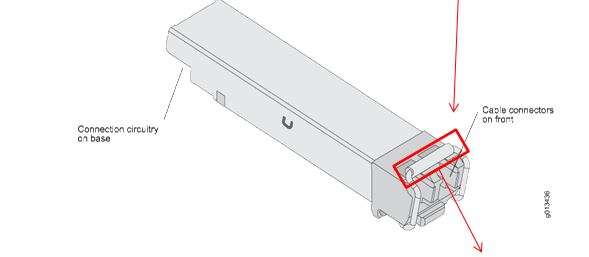
SFP Transmitter and Receiver Wavelengths
Wavelength is one of the most important specifications when selecting an optical SFP transceiver. It describes the optical wavelength used by the module to transmit light through the fibre.
Common wavelengths encountered in fibre networks include:
- 850 nm — commonly associated with short-reach multimode applications
- 1310 nm — widely used for singlemode applications and some other defined optical interfaces
- 1490 nm — used in selected wavelength-specific and bidirectional applications
- 1550 nm — commonly associated with longer-reach singlemode applications and other specialised optical systems
However, wavelength alone does not identify the correct SFP.
Two modules operating at the same nominal wavelength may support different data rates, transmission distances, optical power levels or host platforms. Therefore, technicians should always check the complete transceiver specification.
Do SFP Colour Codes Identify the Wavelength?
Some manufacturers use coloured pull tabs, latches or labels to help distinguish between transceiver types. However, technicians should not rely on colour alone when selecting an SFP.
Colour conventions can vary between manufacturers and product families. Instead, verify the module label or specification for:
- part number
- data rate
- wavelength
- fibre type
- supported reach
- connector configuration
- host compatibility
This replaces the old article’s black, blue, purple and yellow colour table, which could incorrectly suggest that SFP colour coding follows one universal identification standard.
How BiDi SFP Transceivers Work
A conventional duplex fibre link uses separate fibres for transmit and receive traffic. By contrast, a BiDi SFP uses wavelength-division technology to carry both directions across a single fibre.
The two ends use complementary wavelength combinations.
For example, a simplified pair could operate as:
| End | Transmit | Receive |
|---|---|---|
| SFP A | 1310 nm | 1550 nm |
| SFP B | 1550 nm | 1310 nm |
The exact wavelength pair depends on the selected modules. Therefore, this example should not be treated as the required wavelength combination for every BiDi system.
The important principle is:
Tx wavelength at end A must match the Rx wavelength at end B, and Tx at end B must match Rx at end A.
Consequently, BiDi SFPs normally need to be purchased and installed as complementary pairs.
When Does BiDi Make Sense?
BiDi can provide a practical advantage when fibre availability is limited.
Consider an existing route where all available fibre pairs are already allocated. If the equipment and optical design support BiDi, a single-fibre connection may allow network capacity to be added without installing another fibre pair.
However, designers still need to verify:
- data rate
- fibre type
- complementary wavelength pair
- transmission distance
- connector interface
- optical power budget
- host compatibility
BiDi solves a fibre utilisation problem; it does not remove the normal requirements for correct optical design.
Common SFP Selection and Installation Mistakes
Many SFP problems result from specification mismatches rather than failed transceivers.
Choosing an SFP by Connector Alone
Seeing an LC interface does not tell you whether a module suits the network.
Two LC SFPs may use different fibre types, wavelengths, speeds and transmission reaches. Therefore, connector type should form only one part of the selection process.
Assuming Any SFP Will Work in Any SFP Port
SFP describes a form factor and interface family, but host equipment can impose additional requirements.
Always check the network device’s supported speeds, module types and compatibility requirements.
Mixing Singlemode and Multimode Requirements
The installed fibre and selected optics need to suit each other.
Do not choose a transceiver before identifying the fibre type already installed between the two endpoints.
Mismatching BiDi Modules
BiDi optics require complementary transmit and receive wavelengths.
Using two identical modules at opposite ends may result in a failed link because their optical transmitters and receivers do not form the required wavelength pair.
Selecting Optics by Maximum Distance
A module advertised for a much longer distance is not automatically a better choice for a short link.
Instead, select optics that suit the actual fibre route and verify that the optical power levels remain within the operating range of the receivers.
Assuming SFP+ Automatically Supports 1G SFP
Some SFP+ host ports support compatible 1G SFP modules, while others have limitations.
Check the host equipment rather than assuming backward compatibility from the physical form factor.
For the broader network-speed decision, this is also where your existing 1G vs 10G article should remain the detailed owner rather than duplicating that comparison here.
Ignoring Connector Cleanliness
A correct transceiver can still produce poor link performance when contaminated fibre connectors introduce excessive loss.
Inspect and clean optical interfaces before connection where appropriate. fibreSales supplies fibre inspection microscopes and fibre cleaning products for this purpose.
Removing Dust Caps Too Early
Leave protective caps fitted until you are ready to make the optical connection.
This reduces unnecessary exposure of the optical interface to airborne contamination.
SFP Compatibility and Vendor Coding
SFP compatibility involves two separate questions:
Is the transceiver technically suitable for the link?
and:
Will the host equipment accept and operate with that transceiver?
The first question involves speed, fibre type, wavelength, reach, connector and optical characteristics.
The second depends on the network equipment.
Some manufacturers use transceiver identification and validation mechanisms that can generate warnings or restrict unsupported modules. Behaviour can also vary between equipment families and software versions.
Therefore, a third-party SFP should be selected against the specific host platform, not merely the manufacturer’s brand name.
For Cisco equipment, continue to Cisco SFP Compatibility Confusion for the dedicated compatibility discussion.
Real-World SFP Selection Example
Consider a network that needs to connect two switches located in separate buildings.
Before selecting an SFP, the technician determines:
- required network speed
- SFP/SFP+ capability of both switches
- installed fibre type
- actual route distance
- number of available fibre strands
- connector interface
- required wavelength
- host-equipment compatibility
Suppose the existing route uses suitable singlemode fibre and provides a conventional duplex fibre pair.
The technician should then choose compatible optics at both ends that support the required speed and distance over that fibre.
If only one fibre strand remains available, a compatible BiDi pair may provide an alternative, provided the modules use complementary wavelengths and the complete optical link remains within specification.
If the required bandwidth is also being reconsidered, this is where the dedicated 1G vs 10G article should guide the speed decision rather than duplicating that comparison within this SFP guide.
Finally, the technician should verify the optical budget where necessary and confirm that both network devices support the selected transceivers before purchase.
This sequence avoids a common purchasing mistake: choosing the SFP first and trying to make the network fit it afterwards.
Testing and Troubleshooting an SFP Link
If a newly installed SFP link does not establish correctly, troubleshoot the system methodically rather than immediately assuming the transceiver has failed.
Start by checking:
- Module compatibility — confirm that both host devices support the installed transceivers.
- Data rate — verify that the ports and modules operate at compatible speeds.
- Fibre type — confirm that the optics match the installed singlemode or multimode fibre.
- Wavelengths — check both ends, particularly on BiDi links.
- Tx/Rx path — on duplex links, ensure the transmit path at one end reaches the receive path at the other.
- Connector condition — inspect and clean optical interfaces where required.
- Link distance and loss — confirm that the optical path remains within the transceiver’s operating requirements.
- Port configuration — check the network equipment for configuration errors, alarms or unsupported-transceiver messages.
Where physical fibre performance needs further investigation, appropriate fibre test equipment can help separate a transceiver problem from a cabling problem.
For the broader testing workflow, see the Fibre Optic Testing Guide.
Engineering Decision: Diagnose the Link as a System
When an SFP link fails, avoid replacing components randomly.
Work through:
Host → Module → Connector → Fibre → Connector → Module → Host
This approach helps determine whether the problem originates with the transceiver, equipment configuration, contamination or the fibre link itself.

SFP Standards and Best Practice
SFP transceivers operate within established networking and optical-interface specifications. However, selecting a standards-based module does not automatically guarantee that every transceiver will work in every host device.
Network designers should consider both the transmission standard and the requirements of the switch, router, media converter or other equipment at each end of the link.
For Ethernet applications, relevant specifications come from the IEEE 802.3 family of Ethernet standards. These define physical-layer requirements for technologies such as Gigabit Ethernet and 10 Gigabit Ethernet.
SFP and SFP+ form factors also use industry multi-source agreements, or MSAs, which define mechanical and electrical characteristics that allow manufacturers to produce interoperable module formats.
In practice, technicians should verify:
- Ethernet application and required data rate
- host-port capability
- transceiver specification
- fibre type
- wavelength
- supported reach
- connector interface
- optical power requirements
- vendor compatibility
- operating environment
Standards establish the technical framework, while the equipment manufacturer’s specifications determine what a particular port actually supports.
Best Practice for SFP Installation and Maintenance
A consistent installation process helps reduce avoidable faults.
Before installing an SFP:
- confirm the module part number and specifications
- verify compatibility with the host equipment
- check the required data rate
- confirm singlemode or multimode fibre
- verify wavelength and reach
- check that BiDi modules form the correct complementary pair where applicable
- leave dust caps fitted until connection
- inspect and clean fibre connectors as required
During installation:
- orient the transceiver correctly
- never force the module into the SFP cage
- connect the correct fibre interface
- avoid excessive stress on fibre patch leads
- maintain suitable fibre bend radius
- confirm Tx/Rx polarity on duplex connections
- check the host device for link status or transceiver warnings
After installation:
- verify the expected link speed
- investigate alarms rather than ignoring them
- document module locations where appropriate
- protect unused optical ports
- retain suitable spare modules for critical infrastructure where operational requirements justify them
These practices are particularly valuable in networks containing many similar-looking transceivers, where an incorrect module can easily enter the wrong link.
Frequently Asked Questions About SFP Transceivers
What does SFP stand for?
SFP stands for Small Form-factor Pluggable. It describes a compact, removable transceiver format used in compatible switches, routers, media converters and other network equipment.
What does an SFP transceiver do?
An SFP provides the interface between compatible host equipment and the selected transmission medium. Optical SFPs transmit and receive optical signals over fibre, while copper SFP modules can provide an electrical Ethernet interface where supported.
Are SFP modules hot-pluggable?
Yes. SFP modules use a hot-pluggable design. However, technicians should still follow the equipment manufacturer’s procedures and handle connected fibre and optical interfaces correctly.
What is the difference between SFP and SFP+?
For common Ethernet applications, SFP is associated with Gigabit Ethernet, while SFP+ commonly supports 10 Gigabit Ethernet.
The similar physical form factor does not guarantee interchangeability.
For the broader bandwidth decision, use the dedicated 1G vs 10G guide rather than selecting solely from the module form factor.
Can I use a 1G SFP in a 10G SFP+ port?
Some SFP+ ports support compatible 1G SFP modules, but others do not. Check the specifications and configuration requirements of the actual host equipment before assuming backward compatibility.
Can I use an SFP+ module in an SFP port?
A standard 1G SFP port should not be assumed to support a 10G SFP+ transceiver. The host port must support the module type and required operating rate.
Are all SFP transceivers compatible with all switches?
No. A module may physically fit while remaining unsupported by the host equipment.
Check the required data rate, module specification and vendor compatibility for the actual switch or network device.
What is the difference between singlemode and multimode SFPs?
Singlemode and multimode transceivers suit different optical fibre systems and applications.
Multimode optics commonly support shorter links, while singlemode optics support a wide range of longer-distance applications. Always match the transceiver to the installed fibre and required Ethernet application.
What wavelength does an SFP use?
There is no single wavelength for all SFP transceivers.
Depending on the application, modules may operate around wavelengths such as 850 nm, 1310 nm, 1490 nm or 1550 nm. Check the individual transceiver specification.
What is a BiDi SFP?
A BiDi SFP transmits and receives over a single fibre by using different wavelengths for each direction.
BiDi modules normally operate as complementary pairs, so the transmit wavelength at one end corresponds with the receive wavelength at the other.
Can I connect two identical BiDi SFPs?
Usually, a BiDi link requires complementary modules rather than two modules with identical transmit and receive wavelength arrangements.
Always verify the Tx and Rx wavelengths of both transceivers before installation.
How far can an SFP transmit?
Transmission distance depends on the individual module, fibre type, wavelength, Ethernet application and optical characteristics.
Rather than choosing from a generic distance category, check the manufacturer’s specified reach and ensure the complete link operates within the required optical budget.
Do SFP colour codes identify the module?
Colour can provide a visual clue on some manufacturers’ products, but technicians should not treat it as a universal identification method.
Use the module label, part number and technical specifications to confirm wavelength, speed and application.
Why is my SFP link not working?
Common causes include:
- unsupported transceivers
- incorrect port speed
- mismatched fibre type
- incorrect wavelength pairing
- reversed or incorrect Tx/Rx paths
- contaminated connectors
- excessive link loss
- incorrect BiDi pairing
- host configuration problems
Diagnose the complete link systematically before replacing equipment.
Do I need to clean fibre connectors before connecting an SFP?
Inspecting and cleaning optical connector interfaces as required is good fibre-network practice. Contamination can introduce loss even when the SFP and fibre specifications are otherwise correct.
fibreSales supplies fibre cleaning products and fibre inspection microscopes for professional fibre maintenance.
Why Choose fibreSales for SFP Transceivers?
Choosing an SFP involves more than matching a module to a slot. The transceiver must suit the network speed, host equipment, fibre type, wavelength, transmission distance and connector configuration.
fibreSales supplies optical transceiver solutions for Australian networking, telecommunications, data-centre and industrial applications.
For Gigabit Ethernet requirements, explore the 1.25G SFP transceiver range.
For compatible 10 Gigabit Ethernet networks, see the 10G SFP+ transceiver range.
Customers can also source supporting fibre infrastructure including fibre patch leads, fibre cleaning products and fibre inspection equipment.
By considering the complete optical link rather than the transceiver alone, network designers can select an SFP that fits both the equipment and the actual application.
Conclusion
SFP transceivers give network designers a flexible way to connect compatible equipment across fibre optic or copper links. However, the physical SFP form factor represents only one part of the selection process.
The correct transceiver must match the required data rate, host port, fibre type, wavelength, transmission distance, connector interface and network architecture.
For conventional duplex fibre, technicians must also confirm the correct transmit and receive paths. Meanwhile, BiDi links require complementary wavelength pairs, and vendor-specific equipment may introduce additional compatibility requirements.
Therefore, the safest selection process starts with the network link and works towards the module:
Speed → Port → Fibre → Wavelength → Distance → Connector → Optical budget → Compatibility
For professional SFP transceivers, fibre optic connectivity products, technical resources and installation solutions, visit www.fibresales.com.au.
Continue Learning
- 1G vs 10G — use the dedicated fibreSales guide when deciding which network speed suits the application.
- Cisco SFP Compatibility Confusion — understand Cisco-specific transceiver compatibility considerations.
- Fibre Optic Power Budget Calculator Guide — calculate how fibre, connector and splice losses affect optical margin.
- Fibre Optic Testing Guide — understand how to test and troubleshoot installed fibre links.
References
- IEEE 802.3 Ethernet Standards
- ISO/IEC 11801 Generic Cabling for Customer Premises
- BICSI Telecommunications Distribution Methods Manual