Ethernet Cable Testing Guide | How to Test Network Cables Correctly

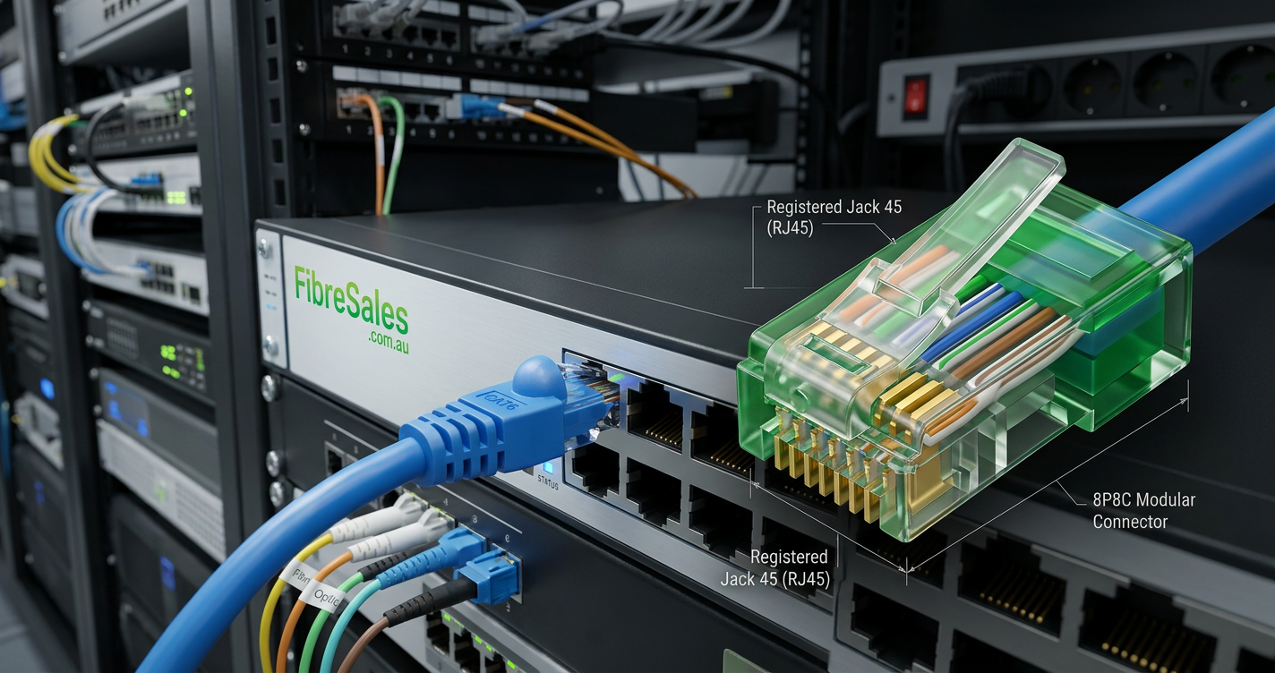
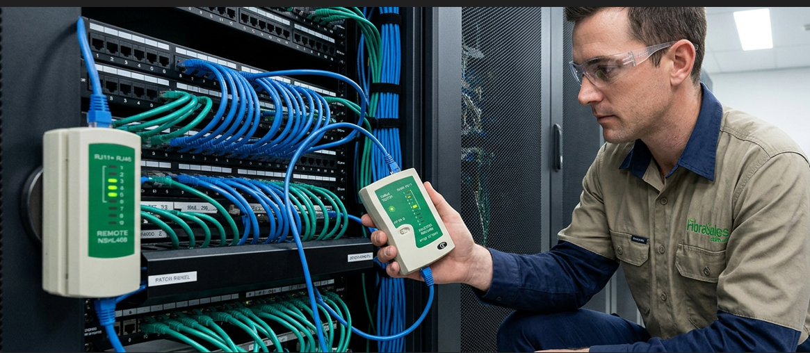
Ethernet Cable Testing using a professional cable tester to verify a Cat6 Ethernet cable.

Ethernet Cable Testing Guide

Testing Ethernet Cables the Right Way

Testing an Ethernet cable is one of the most important steps in any network installation. Even when a cable appears to be terminated correctly, hidden faults such as incorrect pin assignments, split pairs or poor terminations can cause slow network speeds, intermittent connections or complete communication failures.

Whether you’re installing a single workstation, commissioning a structured cabling system or troubleshooting an existing network, testing every cable before it enters service helps identify problems early and reduces costly fault-finding later.

For switch-to-switch connections, workstations and communications cabinets, professionally manufactured Cat6 Patch Cables arrive factory tested and ready for installation. However, whenever you terminate custom Ethernet cables or permanent structured cabling, verifying every connection with the appropriate test equipment is considered industry best practice.

This guide explains the different types of Ethernet cable testing, the equipment used by installers and the faults that cable testers can detect. It complements our RJ45 Pinout: How to Wire Ethernet Cables Step-by-Step guide by focusing on cable verification rather than connector wiring.


What Is Ethernet Cable Testing?

Ethernet cable testing is the process of verifying that a network cable has been installed correctly and is capable of supporting reliable data communication.

Depending on the test equipment being used, testing may confirm:

  • Correct pin-to-pin continuity.
  • Wire map accuracy.
  • Open or short circuits.
  • Reversed conductors.
  • Split pairs.
  • Cable length.
  • Signal quality.
  • Network certification compliance.

Testing is recommended for both newly installed cabling and existing infrastructure during troubleshooting or maintenance.

Professional installers routinely test every completed cable before connecting active network equipment, helping ensure the network performs as intended from the outset.


Why Testing Every Cable Matters

Network faults are often difficult to identify once an installation has been completed. A single incorrectly terminated connector or damaged cable can affect multiple devices, leading to reduced productivity and lengthy troubleshooting.

Testing cables immediately after installation provides several important benefits:

  • Confirms correct termination.
  • Detects wiring faults before commissioning.
  • Reduces return visits.
  • Improves installation quality.
  • Simplifies fault diagnosis.
  • Supports structured cabling best practice.

For organisations installing structured cabling systems, testing also provides confidence that every cable meets the required installation standard before the network goes live.


Types of Ethernet Cable Testing

Not every test measures the same thing. Different testers are designed for different stages of an installation, from basic continuity checks through to comprehensive cable certification.

The most common testing methods include:

Wire Map Testing

A wire map test verifies that each conductor connects to the correct pin at the opposite end of the cable.

It identifies faults including:

  • Open circuits.
  • Short circuits.
  • Crossed wires.
  • Reversed pairs.
  • Split pairs.

This is the most common test performed after terminating Ethernet cables.


Continuity Testing

Continuity testing confirms that each conductor forms a complete electrical path from one end of the cable to the other.

Although continuity testing quickly identifies broken conductors, it does not verify whether the cable will support high-speed Ethernet performance.


Length Testing

Many professional Cable Testers estimate cable length by measuring signal reflections within the cable.

This feature helps installers:

  • Locate damaged sections.
  • Confirm installed cable lengths.
  • Identify unexpected cable joins.
  • Troubleshoot existing infrastructure.

Certification Testing

Certification testing goes beyond basic continuity and wire mapping.

Professional certification equipment measures whether installed cabling complies with recognised performance standards such as the ANSI/TIA-568 Structured Cabling Standard and the ISO/IEC 11801 Generic Cabling Standard.

Certification typically measures:

  • Attenuation.
  • Near-End Crosstalk (NEXT).
  • Return Loss.
  • Propagation Delay.
  • Signal performance.

Certification is generally required for commercial structured cabling projects where documented compliance forms part of the project handover.


Engineering Decision

Testing should never be treated as an optional final step. It forms an essential part of every professional Ethernet installation and helps confirm that the completed cabling will support reliable network communication.

Factory-tested Cat6 Patch Cables minimise installation time and reduce the likelihood of connector faults. When custom cable assemblies or permanent structured cabling are installed, professional Cable Testers provide confidence that every connection has been completed correctly before the network is commissioned.


Choosing the Right Ethernet Cable Tester

Not every Ethernet cable tester performs the same job. Some testers simply verify that each wire is connected correctly, while others analyse signal quality, cable length and compliance with structured cabling standards.

Choosing the right tester depends on the type of work you’re performing, whether you’re terminating a single Ethernet cable or certifying an enterprise network installation.


Basic Continuity Testers

Basic continuity testers provide a quick and economical way to confirm that an Ethernet cable has been terminated correctly.

These testers typically verify:

  • Pin-to-pin continuity.
  • Open circuits.
  • Short circuits.
  • Crossed wires.
  • Reversed pairs.

Basic testers are ideal for:

  • Home networking projects.
  • Small office installations.
  • DIY cable repairs.
  • Verifying custom Ethernet patch leads.

After terminating an Ethernet cable using RJ45 Connectors Explained and the correct wiring sequence from RJ45 Pinout: How to Wire Ethernet Cables Step-by-Step, a continuity test provides immediate confirmation that the cable has been wired correctly.


Wire Map Testers

Wire map testers perform a more detailed analysis by confirming that every conductor terminates on the correct pin at the opposite end of the cable.

Unlike a simple continuity tester, a wire map tester can detect faults that may not be obvious during installation.

Typical faults include:

  • Incorrect pin assignments.
  • Reversed conductors.
  • Split pairs.
  • Open circuits.
  • Short circuits.

Wire map testing is recommended whenever installers terminate custom Ethernet cables using RJ45 Crimping Tools.


Cable Qualification Testers

Qualification testers determine whether an installed Ethernet cable can support a particular network speed.

Rather than simply confirming continuity, these testers evaluate whether the cable can reliably operate at speeds such as:

  • Fast Ethernet (100 Mbps).
  • Gigabit Ethernet (1 Gbps).
  • 2.5 Gigabit Ethernet.
  • 5 Gigabit Ethernet.
  • 10 Gigabit Ethernet.

Qualification testers are particularly useful when upgrading existing buildings where the installed cable category may be unknown.


Cable Certification Testers

Certification testers are the highest level of Ethernet cable testing equipment.

Professional contractors use these instruments to certify that structured cabling installations comply with recognised industry standards, including:

Certification testing measures performance characteristics such as:

  • Near-End Crosstalk (NEXT).
  • Return Loss.
  • Attenuation.
  • Propagation Delay.
  • Insertion Loss.
  • Delay Skew.

Commercial projects often require certification reports before practical completion, providing documented evidence that the installation meets the project specification.


Which Tester Do You Need?

The best tester depends on the work being performed.

Installation TypeRecommended Tester
Home networkingBasic continuity tester
Custom Ethernet patch leadsWire map tester
Office troubleshootingQualification tester
Commercial structured cablingCertification tester
Enterprise installationsCertification tester with reporting capability

For many businesses and electrical contractors, a quality Cable Tester provides the right balance of functionality, portability and ease of use for day-to-day installation and fault-finding.


Engineering Decision

Choosing the correct Ethernet cable tester saves time, reduces troubleshooting and improves installation quality. A basic continuity tester is suitable for occasional cable repairs, while professional installers benefit from wire map or qualification testing during routine installations. For commercial structured cabling projects, certification testing provides documented compliance with recognised industry standards.

Regardless of the tester used, every completed Ethernet cable should be verified before being connected to active network equipment. Combined with professionally manufactured Cat6 Patch Cables, quality Cable Testers help deliver reliable, high-performance Ethernet networks with confidence.

How to Test an Ethernet Cable

Testing an Ethernet cable correctly helps ensure reliable network performance before the cable is connected to active equipment. Whether you’re verifying a factory-terminated patch lead or checking a custom installation, following a consistent testing procedure reduces installation errors and simplifies troubleshooting.

The exact process depends on the type of tester you’re using, but the general workflow remains the same.


Step 1 – Inspect the Cable

Before connecting a cable tester, carry out a visual inspection of the cable and connectors.

Check for:

  • Damaged cable jackets.
  • Bent or broken RJ45 locking tabs.
  • Poorly crimped connectors.
  • Kinks or crushing.
  • Excessive cable bending.
  • Signs of moisture or contamination.

Many cable faults can be identified before electronic testing even begins.

If you’re creating custom Ethernet cables, quality RJ45 Connectors, RJ45 Crimping Tools and Wire Strippers help produce more consistent terminations.


Step 2 – Connect the Cable Tester

Connect one end of the Ethernet cable to the main testing unit and the opposite end to the remote unit.

Most handheld Cable Testers automatically detect the cable and begin testing once connected.

For installed structured cabling, the remote unit is typically connected at the wall outlet or patch panel while the tester remains in the communications cabinet.


Step 3 – Run the Test

Start the testing sequence and allow the tester to complete its analysis.

Depending on the tester, it may check:

  • Wire map.
  • Continuity.
  • Cable length.
  • Split pairs.
  • Open circuits.
  • Short circuits.
  • Reversed conductors.
  • Signal quality.

Professional qualification and certification testers perform additional measurements to verify that installed cabling supports the required Ethernet performance.


Step 4 – Interpret the Results

Once testing is complete, review the results before placing the cable into service.

A successful test normally confirms:

  • All eight conductors terminate correctly.
  • No wiring faults are present.
  • Pin assignments match at both ends.
  • The cable is suitable for its intended application.

If faults are detected, correct the termination before connecting the cable to network equipment.

When troubleshooting wiring problems, refer to RJ45 Pinout: How to Wire Ethernet Cables Step-by-Step to verify the correct conductor sequence.


Common Ethernet Cable Faults

Professional cable testers identify a range of installation faults that may not be visible during a visual inspection.

Open Circuit

An open circuit occurs when one or more conductors fail to make electrical contact between each end of the cable.

Typical causes include:

  • Poor crimping.
  • Broken conductors.
  • Damaged connectors.

Short Circuit

A short circuit occurs when two conductors unintentionally contact each other.

This usually results from damaged insulation or incorrect termination and prevents reliable Ethernet communication.


Reversed Pair

A reversed pair occurs when the conductors within a twisted pair terminate in the wrong order.

Although the cable may appear correctly wired, communication problems often occur because the transmit and receive signals no longer align correctly.


Split Pair

Split pairs are among the most difficult faults to detect without a cable tester.

This fault occurs when conductors remain electrically connected but the twisted pairs have been mixed incorrectly.

Although continuity may appear correct, split pairs significantly increase crosstalk and often prevent reliable Gigabit Ethernet communication.


Incorrect Pin Assignment

Using an incorrect conductor sequence during termination results in wiring faults that prevent normal network operation.

Always terminate cables according to recognised wiring standards and verify every completed cable using a Cable Tester before installation.


Real-World Example

A contractor installs several custom-length Cat6 Ethernet cables between a patch panel and network switch in a new office fit-out. Every cable appears correctly terminated during visual inspection.

Before commissioning the network, each cable is tested using a professional Cable Tester. One cable reports a split-pair fault that would have caused intermittent Gigabit Ethernet performance.

After re-terminating the connector and retesting, the cable passes successfully, allowing the contractor to complete the installation with confidence and avoiding a costly return visit.


Engineering Decision

Testing every Ethernet cable before commissioning is one of the simplest ways to improve installation quality and reduce future troubleshooting. Even experienced installers can encounter wiring faults that are difficult to identify without dedicated test equipment.

Professionally manufactured Cat6 Patch Cables minimise the need for field termination and arrive factory tested. When installing custom Ethernet cables or structured cabling infrastructure, combining quality installation tools with professional Cable Testers helps ensure every connection performs reliably from day one.

Advanced Ethernet Cable Testing

Basic continuity testing confirms that an Ethernet cable has been wired correctly, but professional network installations often require more comprehensive testing. Advanced testing evaluates the cable’s ability to carry high-speed data reliably, ensuring the completed installation meets the performance requirements of modern Ethernet networks.

Electrical contractors, data centre technicians and structured cabling installers commonly perform advanced testing during network commissioning to verify that every cable supports the required application before the network goes live.


Qualification Testing vs Certification Testing

Although these terms are often used interchangeably, qualification testing and certification testing perform different functions.

Qualification Testing

Qualification testing determines whether an installed Ethernet cable can support a particular network application or data rate.

Typical qualification tests verify support for:

  • 100 Mbps Ethernet.
  • 1 Gigabit Ethernet.
  • 2.5 Gigabit Ethernet.
  • 5 Gigabit Ethernet.
  • 10 Gigabit Ethernet.

Qualification testing provides confidence that existing cabling can support upgraded network equipment without replacing the installed infrastructure.


Certification Testing

Certification testing provides the highest level of verification.

Rather than simply confirming that a cable works, certification testing measures whether the installed cabling complies with recognised structured cabling standards.

Professional certification equipment evaluates performance characteristics including:

  • Insertion Loss.
  • Near-End Crosstalk (NEXT).
  • Power Sum NEXT (PSNEXT).
  • Return Loss.
  • Attenuation.
  • Propagation Delay.
  • Delay Skew.
  • Alien Crosstalk (where applicable).

Certification testing is widely specified for commercial projects because it provides documented evidence that the completed installation complies with recognised industry standards such as the ANSI/TIA-568 Structured Cabling Standard and the ISO/IEC 11801 Generic Cabling Standard.


Common Causes of Ethernet Cable Failures

Even correctly installed cabling can develop faults over time if cables are subjected to excessive mechanical stress or poor installation practices.

Common causes include:

Damaged Connectors

Broken locking tabs, poorly crimped connectors or worn contacts can lead to intermittent network connections.

Where connectors become damaged, replacing the connector or using a professionally manufactured Cat6 Patch Cable is often the quickest solution.


Excessive Cable Bending

Twisted-pair Ethernet cable has a minimum bend radius.

Sharp bends or repeated flexing can damage the cable’s internal geometry, increasing crosstalk and reducing signal performance.

Professional installers avoid tight bends when routing Ethernet cables through communications cabinets and cable trays.


Cable Damage During Installation

Cable jackets may become damaged during installation if excessive pulling force is applied or cables are routed across sharp edges.

Damaged insulation can eventually lead to intermittent faults that are difficult to diagnose without specialist test equipment.


Poor Terminations

Incorrectly terminated connectors remain one of the most common causes of Ethernet faults.

Using quality RJ45 Crimping Tools together with the correct wiring sequence from RJ45 Pinout: How to Wire Ethernet Cables Step-by-Step significantly reduces termination errors.


Best Practices for Reliable Ethernet Testing

Professional installers follow consistent testing procedures to improve installation quality and simplify future maintenance.

Recommended best practices include:

  • Test every cable immediately after termination.
  • Label cables before testing.
  • Record test results for commercial installations.
  • Inspect connectors before connecting test equipment.
  • Retest cables after repairs or modifications.
  • Store cable testers in protective cases and calibrate certification equipment as recommended by the manufacturer.

These practices help ensure that testing becomes part of the installation process rather than simply a troubleshooting exercise.


Real-World Installation Example

A contractor completes the structured cabling for a new medical facility using Cat6 horizontal cabling terminated into Keystone Jacks. Before handing over the project, every cable undergoes certification testing against the project specification.

During testing, one cable fails due to excessive return loss caused by an incorrectly terminated connector. After replacing the connector and repeating the test, the cable achieves a passing result.

By identifying the fault before commissioning, the contractor avoids future network issues, reduces warranty risk and delivers documented evidence that the installation complies with recognised structured cabling standards.


Engineering Decision

The level of testing should reflect the importance of the installation. Basic continuity testing is suitable for occasional cable repairs, while qualification testing provides confidence when upgrading existing networks. Commercial structured cabling projects benefit from certification testing because it verifies compliance with recognised industry standards and provides documented results for project handover.

Regardless of the installation size, every completed Ethernet cable should be tested before being connected to active equipment. Combining professional Cable Testers with quality installation practices and factory-tested Cat6 Patch Cables helps deliver reliable, high-performance Ethernet networks while reducing future troubleshooting and maintenance.

Related Posts

Business Cat6 cable installed in a professional office network cabinet

Best Cat6 Patch Cable for Business | Buying Guide

Business Cat6 cable selection affects far more than whether an Ethernet connection works. In a...

rj45-punch-down-tools-explained

RJ45 Punch-down Tools Explained | Complete Installation Guide

RJ45 Punch-down Tools Explained | Complete Installation Guide RJ45 punch-down tools are essential for terminating...

PoE vs PoE+ vs PoE++

PoE vs PoE+ vs PoE++ | Which Power over Ethernet Standard Do You Need?

PoE vs PoE+ vs PoE++ | Which Power over Ethernet Standard Do You Need? What’s...

PoE RJ45 Pinout showing how Power over Ethernet carries data and electrical power through a Cat6 Ethernet cable.

PoE RJ45 Pinout Explained | Power over Ethernet Wiring Guide

RJ45 Pinout Explained What Is a PoE RJ45 Pinout? A PoE RJ45 pinout describes how...

Ethernet Networks Use T568B in Australian commercial structured cabling installations for compatibility and consistency.

Why Most Ethernet Networks Use T568B | Commercial Wiring Standard

Why Most Ethernet Networks Use T568B Why Most Ethernet Networks Use T568B Although both T568A...

What does RJ45 mean

What Does RJ45 Mean?

What Does RJ45 Mean? RJ45 is one of the most recognised terms in computer networking,...