Optical Return Loss (ORL) Explained
Optical Return Loss (ORL) is one of the most misunderstood but critical parameters in fibre optic network performance. While many technicians focus on insertion loss, ORL is equally important—especially in high-speed, high-power, and bidirectional optical systems.
In simple terms, ORL measures how much light is reflected back toward the source in a fibre optic link. Excessive reflections can destabilise lasers, degrade signal integrity, and cause intermittent or hard-to-trace network faults.
This guide explains ORL from first principles through to field testing, troubleshooting, and design considerations used in modern Australian fibre deployments.
What Is Optical Return Loss (ORL)?
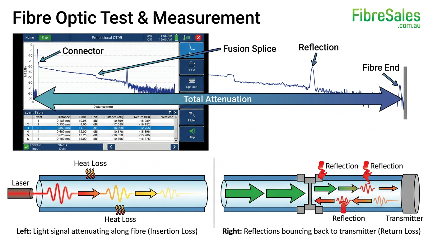
Optical Return Loss is the total amount of reflected optical power returning toward the transmitter, expressed in decibels (dB).
It occurs due to imperfections in the fibre link such as:
- Connector gaps
- Dirty end faces
- Poor splicing
- Refractive index mismatches
- Mechanical reflections in components
ORL in simple terms:
- High ORL (good) = very little reflected light returns
- Low ORL (bad) = significant reflections returning into the system
Optical return loss is always a positive dB value, but higher numbers indicate better performance.
ORL vs Insertion Loss (Critical Distinction)
These two metrics are often confused but measure completely different behaviours:
| Parameter | Measures | Direction | Impact |
|---|---|---|---|
| Insertion Loss | Signal power lost through link | Forward direction | Reduces received power |
| ORL | Reflected light back toward source | Reverse direction | Affects transmitter stability |
A fibre link can have:
- Low insertion loss (good signal strength)
BUT - Poor ORL (high reflections causing instability)
Both must be controlled for a stable system.
Why ORL Matters in Modern Fibre Networks
ORL becomes critical in systems using:
- High-speed data (10G, 25G, 100G+)
- Laser-based transmitters (especially DFB lasers)
- CWDM and DWDM systems
- Long-haul or amplified networks
- Passive optical networks (PON)
Excessive reflections can cause:
- Laser noise and jitter
- Reduced extinction ratio
- Bit errors (BER degradation)
- Transmitter instability or shutdown
- Intermittent link failures that are hard to diagnose
For design context, ORL is often more important than insertion loss in laser-sensitive systems.
What Causes Poor Optical Return Loss?
ORL issues are almost always reflection-based. The most common causes include:
1. Dirty or contaminated connectors
The #1 cause in the field.
Even microscopic dust particles create:
- Fresnel reflections
- Air gaps at the fibre interface
This is why inspection and cleaning are critical before testing.
2. Poorly polished connector end faces
Connector geometry plays a major role:
- Flat polish (UPC) → higher reflections
- Angled polish (APC) → significantly reduced reflections
3. Air gaps in mating connectors
Even a few microns of separation creates a refractive index change that reflects light back.
4. Bad or inconsistent fusion splices
Poor splice alignment or contamination introduces:
- Micro-reflections
- Backscatter irregularities
5. Mechanical stress or macro-bending
Although more associated with loss, severe stress can also introduce reflection points.
6. Mixed connector types (UPC to APC mismatch)
This is a major field issue:
- Causes severe reflection spikes
- Can damage sensitive optical transmitters
ORL and Fresnel Reflections (The Physics Behind It)
Whenever light passes between two materials with different refractive indices (e.g. glass → air), a portion of the light is reflected back.
This is called a Fresnel reflection.
Typical reflection points:
- Connector end faces
- Unmated fibre ends
- Mechanical interfaces
A single poor connector can dominate the ORL of an entire link.
Acceptable ORL Values in Fibre Networks
ORL requirements depend on system type.
| Network Type | Recommended ORL |
|---|---|
| Basic multimode LAN | > 20 dB |
| Singlemode enterprise | > 30 dB |
| High-speed digital systems | > 35 dB |
| CATV / analogue RF overlay | > 45 dB |
| DWDM / coherent systems | > 50 dB |
In general: the higher the ORL, the better the system stability.
UPC vs APC Connectors and ORL Performance
Connector type is one of the biggest determinants of ORL performance.
| Connector Type | Polish Angle | Typical ORL | Use Case |
|---|---|---|---|
| UPC (Ultra Physical Contact) | 0° flat polish | ~ -50 dB reflection | General digital networks |
| APC (Angled Physical Contact) | 8° angle polish | ~ -60 to -75 dB reflection | High-performance, RF, PON |
Key engineering insight:
APC connectors dramatically improve ORL by directing reflected light away from the source.
Mixing APC and UPC connectors is not acceptable in most systems.
How ORL Is Measured
ORL is measured using specialised test equipment:
1. Optical Time Domain Reflectometer (OTDR)
Covered in detail in our guide:
Internal reference: OTDR Event Table Explained
https://fibresales.com.au/otdr-event-table-explained/
OTDRs show:
- Reflection spikes
- Return loss per event
- Fault location mapping
However, OTDRs measure reflections indirectly.
2. Dedicated ORL Meter
An ORL meter:
- Injects a known signal
- Measures total reflected power
- Provides a single ORL value for the entire link
This is preferred for:
- Commissioning tests
- Compliance testing
- System acceptance testing
ORL in Relation to Link Budget
ORL does not directly reduce received signal power like insertion loss, but it affects system performance indirectly.
For context on link design:
Internal reference: Fibre Optic Power Budget Calculator Guide
Poor ORL can:
- Increase noise floor
- Reduce receiver sensitivity margin
- Create unstable BER performance
ORL Testing Best Practices (Field Proven)
Always follow this sequence:
- Inspect fibre end faces
- Clean all connectors properly
- Re-inspect under microscope
- Perform reference calibration (if required)
- Conduct OTDR test
- Confirm ORL meter readings
Engineering Tip:
Never test ORL on dirty fibre.
A single dust particle can reduce ORL by 10–20 dB.
Common Mistakes in ORL Testing
1. Skipping inspection before testing
Leads to false failure diagnosis.
2. Using wrong launch conditions on OTDR
Incorrect launch cables can distort reflection readings.
3. Mixing connector types unknowingly
UPC/APC mismatches cause extreme reflection errors.
4. Ignoring patch lead quality
Low-grade patch leads often dominate ORL issues in short links.
Troubleshooting High ORL in the Field
Step-by-step diagnostic approach:
1st step: Identify reflection spikes on OTDR
- Locate strongest event points
2nd step: Isolate sections
- Patch leads
- Distribution frames
- Splice closures
3rd Step: Clean and re-test
- Focus on connector interfaces first
4th Step: Replace suspect components
- Patch leads are the most common culprit
5th Step: Revalidate system ORL
- Ensure margin meets design specification
Real-World Field Example
A 96-core singlemode backbone link in a data centre showed intermittent packet loss.
Findings:
- Insertion loss: within spec
- ORL: below acceptable threshold (~28 dB)
Root cause:
A batch of contaminated LC patch leads at the cross-connect.
Fix:
- Full connector cleaning
- Replacement of patch leads
- ORL improved to 42 dB
- System stabilised immediately
ORL and OTDR Event Interpretation
Understanding ORL becomes easier when paired with OTDR analysis.
For a deeper breakdown of event interpretation:
Internal reference: OTDR Event Table Explained
Key OTDR indicators of poor ORL:
- High reflection spikes at connectors
- Multiple small reflection events
- Elevated noise floor near source
Engineering Tips for Improving ORL
- Always use APC connectors in high-performance systems
- Maintain strict cleaning protocols
- Avoid unnecessary connector pairs
- Use fusion splicing instead of connectors where possible
- Minimise patch panel congestion
- Use quality-certified patch leads
ORL Decision Guide (Quick Field Reference)
| Symptom | Likely Cause | Action |
|---|---|---|
| Intermittent link drops | Dirty connectors | Clean + re-test |
| High reflection spike | UPC/APC mismatch | Replace connector type |
| Poor ORL across entire link | System-wide contamination | Full re-clean |
| Localised spike on OTDR | Bad patch lead | Replace lead |
FAQ
What is a good ORL value for fibre networks?
Generally, anything above 30 dB is acceptable for enterprise systems, while high-performance systems require 40–50 dB or more.
Can ORL be improved without replacing cable?
Yes. Cleaning connectors and replacing patch leads often resolves ORL issues without re-cabling.
Does fusion splicing improve ORL?
Yes. Fusion splices have extremely low reflection compared to mechanical connectors.
Why does ORL matter more in high-speed networks?
Because modern lasers are highly sensitive to reflected light, which can destabilise transmission and increase bit errors.
Conclusion
Optical Return Loss is a fundamental performance metric that directly impacts the stability and reliability of fibre optic systems. While often overlooked in favour of insertion loss, ORL becomes critical in modern high-speed networks where laser sensitivity and signal integrity are tightly constrained.
Proper connector hygiene, correct connector selection (especially APC), and disciplined testing practices are essential to maintaining high ORL values and ensuring long-term network stability.
- For professional OTDRs , Power Meters, Light Sources, Cleaning Products and Inspection Microscopes, visit www.fibresales.com.au to explore Australia’s growing resource centre for fibre optic products, technical guides and professional testing solutions.