Fibre Test Report Explained: How to Read and Interpret Fibre Optic Test Results
When a fibre optic installation is completed, the job isn’t finished until the network has been tested and documented. A professional fibre test report provides evidence that the installation complies with project specifications, industry standards and customer requirements.
Understanding a fibre test report is just as important as performing the tests themselves. Whether you’re a contractor, network engineer or project manager, knowing how to interpret insertion loss, OTDR results, attenuation and pass/fail criteria helps verify that a fibre network is ready for service.
If you’re new to fibre optic testing, start with our Fibre Optic Testing Performance Guide which explains the overall testing process before examining individual reports in detail.
Professional test reports begin with accurate measurements, which is why technicians rely on quality OTDRs , Power Meters and Light Sources to generate reliable certification results.
What Is a Fibre Test Report?
The official record of all measurements taken during the commissioning, certification or maintenance of a fibre optic network.
Rather than simply stating that a link passed testing, the report documents the measured performance of every fibre and provides evidence that the installation meets the required specification.
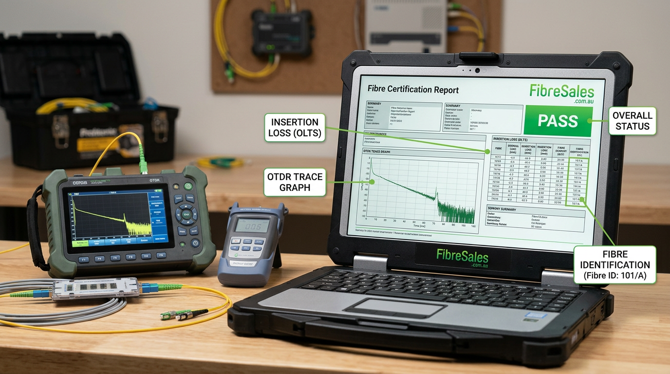
A professional fibre test report typically includes:
- Project details
- Test date and technician
- Fibre identification
- Fibre length
- Test wavelength(s)
- Insertion loss results
- OTDR results
- Pass/fail status
- Equipment used
- Calibration details
This documentation becomes an important reference for future maintenance, warranty claims and network upgrades.
Why a Fibre Test Report Is Important
A fibre test report provides confidence that the installed network performs as designed.
It enables contractors to demonstrate compliance, gives customers confidence in the installation and provides a performance baseline for future troubleshooting.
Without documented test results, identifying whether a fault existed during installation or developed later becomes much more difficult.
Engineering Decision
Never hand over a completed fibre installation without supplying a comprehensive fibre test report. It protects both the installer and the customer by documenting the network’s condition at the time of commissioning.
What Should Every Fibre Test Report Include?
Every fibre test report should contain enough information for another technician to understand how the network was tested and whether it complies with the design specification.
A complete report should include:
| Report Section | Purpose |
|---|---|
| Project information | Identifies the installation |
| Cable identification | Matches fibres to drawings |
| Test equipment | Confirms instruments used |
| Calibration dates | Demonstrates measurement validity |
| Test wavelengths | Verifies correct testing methodology |
| Fibre length | Confirms installed distance |
| Insertion loss | Measures total attenuation |
| OTDR trace | Identifies events and faults |
| Pass/Fail status | Indicates compliance |
| Technician details | Provides accountability |
Missing information can reduce the value of the report and make future troubleshooting more difficult.
Understanding Insertion Loss in a Fibre Test Report
Insertion loss is one of the most important measurements recorded in a fibre test report because it confirms how much optical power has been lost across the complete fibre link.
(IL) Insertion Loss should always be compared with the calculated loss budget rather than assessed in isolation.
If you need a refresher on interpreting these values, read our Insertion Loss vs Return Loss Explained article and our Fibre Optic Power Budget Calculator Guide .
Professional insertion loss testing should always be performed using a calibrated Power Meter and matching Light Source .
http://(https://fibresales.com.au/insertion-loss-vs-return-loss-explained-understanding-the-difference-in-fibre-optic-testing/)
Understanding OTDR Results in a Fibre Test Report
Many professional fibre test reports also include OTDR traces.
These traces allow technicians to identify:
- Connector locations
- Fusion splice performance
- Reflective events
- Fibre breaks
- Excessive attenuation
- Fibre length
Rather than relying only on the graphical trace, technicians should also review the event table.

Our OTDR Event Table Explained guide explains how to interpret every event within the report.
Understanding Pass/Fail Results in a Fibre Test Report
A fibre test report normally concludes with a pass or fail result for each fibre.
A “Pass” means the measured values comply with the project specification or applicable industry standard.
A “Fail” simply indicates that one or more measured values exceed the acceptable limits. It does not automatically mean the cable requires replacement.
Typical reasons for failed results include:
- Dirty connectors
- Damaged patch leads
- Poor fusion splices
- Excessive bending
- Incorrect reference method
- Testing at the wrong wavelength
Many failed tests can be corrected without replacing the installed cable.
Common Mistakes When Reading a Fibre Test Report
Even experienced technicians sometimes misinterpret test reports.
Common mistakes include:
- Looking only at the pass/fail result.
- Ignoring insertion loss values.
- Overlooking reflective OTDR events.
- Comparing results from different wavelengths.
- Assuming every failed result indicates cable damage.
- Ignoring equipment calibration dates.
Common Mistake
A pass result does not necessarily indicate an optimised installation. A link may pass the specification while still containing connectors or splices that could benefit from improvement.
How to Verify a Fibre Test Report
Before accepting a completed installation, verify:
- Equipment calibration is current.
- Correct wavelengths were used.
- Fibre identification matches the design drawings.
- Insertion loss is within specification.
- OTDR traces appear consistent.
- Pass/fail criteria match the project requirements.
- Results have been properly documented.
If unexpected attenuation is identified, follow our Fibre Troubleshooting Guide and Fibre Connector Troubleshooting Guide to systematically identify the cause.
Real-World Field Scenario
A contractor submitted a fibre test report showing several failed links within a new commercial building.
Rather than immediately replacing the installed cable, the project engineer reviewed the report and noticed the reference values had been established using contaminated reference leads.
After inspecting the connectors with a Microscope and cleaning them using professional Cleaning Products, the technician reset the reference and repeated the insertion loss tests.
All fibres subsequently passed, avoiding unnecessary rework and reducing project delays.
Best Practices for Creating a Fibre Test Report
To produce a reliable fibre test report:
- Inspect and clean connectors before testing.
- Use calibrated test equipment.
- Follow recognised reference methods.
- Test at all required wavelengths.
- Record both insertion loss and OTDR results where specified.
- Save electronic copies of all reports.
- Archive results for future maintenance and warranty purposes.
Consistent documentation supports efficient fault finding and simplifies future network upgrades.
Engineering Decision Insight
A fibre test report is more than a collection of measurements—it is the documented proof that a fibre optic installation has been tested, verified and commissioned correctly.
Understanding how to interpret insertion loss, OTDR traces, attenuation and pass/fail criteria enables engineers to identify genuine problems, avoid unnecessary repairs and maintain confidence in the network’s long-term performance.
Producing comprehensive, accurate fibre test reports also demonstrates professionalism, supports warranty compliance and provides a valuable benchmark for future maintenance.
References
For further guidance, refer to: