Insertion Loss vs Return Loss Explained: Understanding the Difference in Fibre Optic Testing
Introduction
Insertion loss and return loss are two of the most important measurements in fibre optic testing, yet they are often confused because both relate to signal quality. While they are measured in decibels (dB), they describe completely different aspects of optical performance.
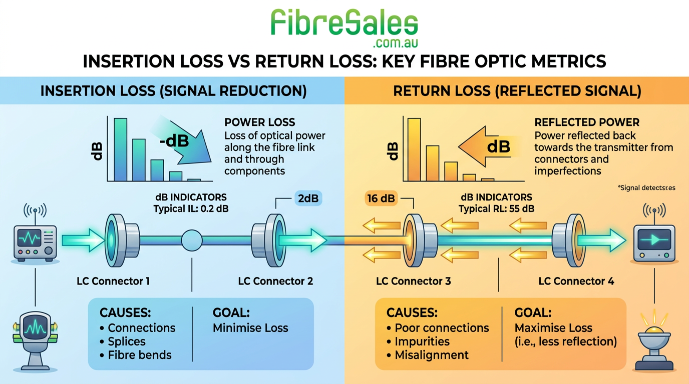
Insertion loss measures how much optical power is lost as light travels through a fibre link, whereas return loss measures how much light is reflected back towards the transmitter. Understanding the difference is essential when commissioning new installations, troubleshooting faults, or verifying that a network meets industry performance standards.
We’ll explain how both measurements are taken, why they matter, and how to interpret the results correctly. If you’re new to fibre testing, our Fibre Optic Testing Performance Guide provides an excellent overview before exploring these measurements in greater depth. When testing installed networks, using quality OTDRs, optical power meters, light sources, and inspection microscopes from FibreSales helps ensure accurate and repeatable results.
related Fibre Optic Testing Performance Guide Australia
What Is Insertion Loss?
Insertion loss is the reduction in optical power that occurs as light passes through a fibre optic link.
Every component contributes some degree of loss, including:
- Fibre optic cable
- Connectors
- Fusion splices
- Mechanical splices
- Adaptors
- Patch panels
The total insertion loss is the combined attenuation of every component within the link.
For a detailed explanation of attenuation and how it affects network performance, see our Fibre Optic Attenuation Troubleshooting Guide.
Engineering Tip
Always clean connectors before measuring insertion loss. Contaminated ferrules remain one of the leading causes of unexpectedly high attenuation.
What Is Return Loss?
Return loss measures the amount of optical power reflected back towards the transmitter.
Higher return loss values indicate better connector performance because less light is reflected.
Return loss is heavily influenced by:
- Connector polish
- Connector cleanliness
- Fibre end-face quality
- Air gaps
- Mechanical damage
Return loss becomes increasingly important in high-speed singlemode networks where optical reflections can affect laser stability.
Insertion Loss vs Return Loss: What’s the Difference?
| Characteristic | Insertion Loss | Return Loss |
|---|---|---|
| Measures | Power lost through the link | Power reflected back towards the source |
| Preferred Value | Lower | Higher |
| Units | dB | dB |
| Main Causes | Attenuation, splices, connectors | Dirty connectors, poor polishing, reflections |
| Common Test Equipment | Optical Power Meter, Light Source, OTDR | OTDR, Return Loss Meter |
| Affects | Link budget | Signal quality and laser stability |
Although both measurements use decibels, they should never be interpreted in the same way.
Engineering decision
If insertion loss is within specification but return loss is poor, inspect the connector end faces before investigating the fibre cable itself.
Why Both Measurements Matter
A fibre link may pass insertion loss testing while still suffering from excessive reflections.
For example:
- A connector may introduce very little attenuation.
- However, contamination or poor polishing can create high reflectance.
- The link appears operational but may experience intermittent errors or reduced performance.
This is why many technicians combine insertion loss testing with OTDR analysis. Our OTDR Event Table Explained guide explains how reflective events appear during OTDR testing and how to interpret them accurately.
Typical Causes of High Insertion Loss
Common causes include:
- Dirty connectors
- Damaged ferrules
- Poor fusion splices
- Excessive bend radius
- Incorrect adaptor alignment
- Fibre damage
- Low-quality patch leads
If unexplained attenuation is detected, work through a structured troubleshooting process using our Fibre Connector Troubleshooting Guide and Fibre Troubleshooting Guide before replacing network equipment.
Typical Causes of Poor Return Loss
Return loss problems are usually caused by optical reflections rather than attenuation.
Common causes include:
- Dirty connector end faces
- UPC connectors used where APC connectors are required
- Air gaps
- Damaged connector polish
- Poorly terminated connectors
- Mechanical stress
Cleaning the connector with a quality One-Click Cleaner and inspecting it using a fibre inspection microscope should always be the first step before replacing components.
Common Mistake
Many technicians assume every reflective OTDR event indicates a faulty connector. In reality, some reflections are expected and should be assessed alongside insertion loss, reflectance values and connector condition.
How Insertion Loss and Return Loss Affect Different Networks
Data Centres
High-density patching increases the number of connector interfaces, making both insertion loss and return loss important.
Telecommunications
Long-distance singlemode networks are particularly sensitive to optical reflections because laser transmitters operate over greater distances.
Passive Optical Networks (PON)
Splitters increase insertion loss while connector quality significantly affects return loss.
Enterprise Networks
Poor patch lead quality can increase attenuation and reflections, reducing long-term reliability.
Measuring Insertion Loss and Return Loss
Professional testing normally includes:
- Optical Light Source
- Optical Power Meter
- OTDR
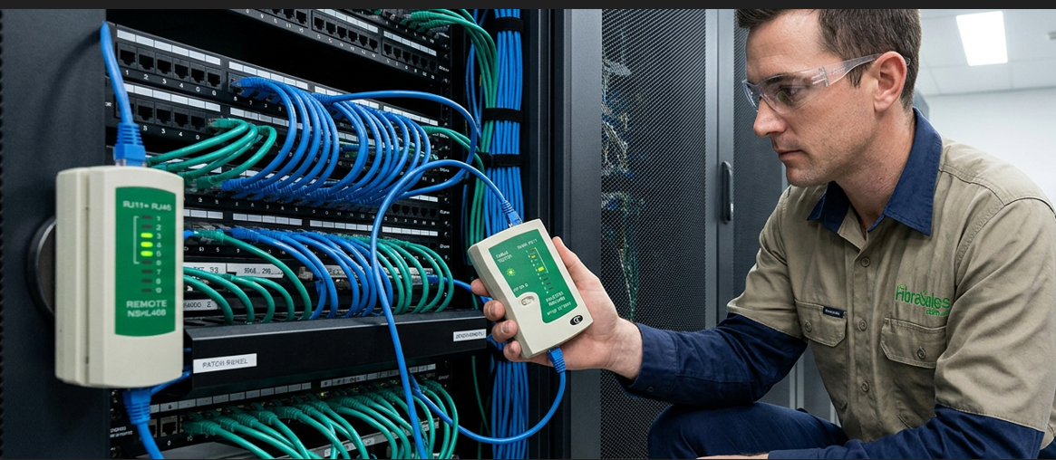
- Inspection Microscope
- Fibre Cleaning Kit
Each instrument measures a different aspect of optical performance.
For guidance on selecting the right equipment, browse the FibreSales range of fibre optic testing equipment, including OTDRs, power meters, inspection microscopes, light sources and cleaning products.
Real-World Field Scenario
A customer reported intermittent errors on a 10G singlemode link despite acceptable insertion loss readings.
Testing showed:
- Insertion Loss: Within specification
- Return Loss: Poor at one connector
- OTDR: Reflective event at the patch panel
Inspection revealed contamination on an APC connector.
After cleaning the connector and retesting:
- Return loss improved significantly.
- OTDR reflections reduced.
- Eliminating network errors without replacing any hardware.
Demonstrating why both insertion loss and return loss should be evaluated together rather than independently.
Engineering Decision Insight
Insertion loss tells you how much signal has been lost, while return loss tells you how much signal has been reflected. Together they provide a complete picture of fibre optic link performance.
Professional technicians rarely rely on a single measurement. Instead, they combine insertion loss testing, return loss analysis, OTDR traces and connector inspection to accurately diagnose faults and verify network performance.
When commissioning or maintaining fibre optic infrastructure, investing in quality test equipment and following recognised testing procedures reduces troubleshooting time and helps prevent unnecessary component replacement.
Whether you’re commissioning a new installation or troubleshooting an existing fibre network, FibreSales supplies the professional testing equipment and installation products needed to achieve reliable results. For professional OTDRs , Power Meters, Light Sources, Cleaning Products and Inspection Microscopes, visit www.fibresales.com.au to explore Australia’s growing resource centre for fibre optic products, technical guides and professional testing solutions.