Optical Power Meter Guide: How to Test Fibre Optic Networks Accurately
Testing a fibre optic network without an optical power meter is like diagnosing a vehicle without measuring engine performance. While an Optical Time Domain Reflectometer (OTDR) identifies where faults occur, an optical power meter confirms whether the complete fibre link performs within specification.
Whether you’re commissioning a new installation, maintaining an existing network or troubleshooting unexpected attenuation, an optical power meter is one of the most important instruments in any fibre technician’s toolkit.
If you’re new to fibre optic testing, our Fibre Optic Testing Performance Guide (https://fibresales.com.au/fibre-optic-testing-performance-guide-australia/) provides an overview of testing methodologies before exploring individual instruments in greater detail.
What Is an Optical Power Meter?
An optical power meter is a precision instrument that measures the amount of optical power travelling through a fibre optic cable.
Unlike an OTDR, which analyses reflected light to identify faults, a power meter measures the actual optical power received at the opposite end of the link. This makes it the preferred instrument for insertion loss testing and network certification.
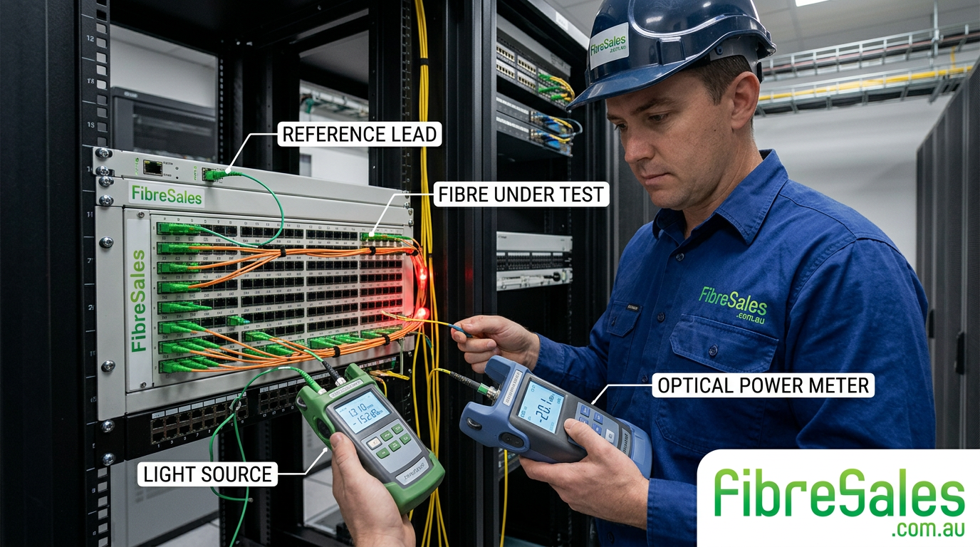
When used together with a calibrated light source, the power meter accurately determines whether the installed fibre link meets the design requirements.
Professional fibre technicians typically use power meters when:
- Commissioning new fibre installations
- Verifying fibre optic patch leads
- Measuring insertion loss
- Troubleshooting attenuation
- Testing repaired fibre links
- Performing preventative maintenance
If excessive attenuation is detected during testing, our Fibre Optic Attenuation Troubleshooting Guide (https://fibresales.com.au/fibre-optic-attenuation-troubleshooting-guide/) explains the most common causes and corrective actions.
How Does an Optical Power Meter Work?
A stable optical light source injects a known amount of optical power into one end of the fibre.
The optical power meter measures how much optical power arrives at the opposite end.
The difference between transmitted power and received power represents the insertion loss of the complete fibre link.
This simple process provides one of the most accurate methods of verifying overall network performance.
For reliable measurements, always use a quality Light Source (https://fibresales.com.au/shop/jsf/epro-loop-builder:products/tax/product_cat:4151/) that matches the operating wavelengths of the network being tested.
Optical Power Meter Guide: Why Is Reference Setting So Important?
Before any insertion loss measurement is taken, the power meter and light source must be correctly referenced.
The reference establishes the baseline optical power against which all future measurements are compared.
Incorrect referencing is one of the most common causes of inaccurate test results.
Engineering Tip
Always establish the reference using clean reference leads of known quality. Never assume previously used reference cables remain suitable without inspection.
Before setting the reference, inspect every connector using a Fibre Inspection Microscope (https://fibresales.com.au/shop/jsf/epro-loop-builder:products/tax/product_cat:4208/) and clean them using professional Cleaning Products (https://fibresales.com.au/shop/jsf/epro-loop-builder:products/tax/product_cat:3953/). Even microscopic contamination can significantly affect measurement accuracy.
What Does an Optical Power Meter Measure?
An optical power meter measures:
- Optical power (dBm)
- Optical loss (dB)
- Insertion loss
- Received optical signal strength
These measurements help verify that the installed network performs within the design power budget.
For a detailed explanation of optical budgets, read our Fibre Optic Power Budget Calculator Guide (https://fibresales.com.au/fibre-optic-power-budget-calculator-guide-understanding-link-loss-and-system-limits/).
Optical Power Meter Guide: Understanding dBm and dB
One of the most confusing topics for new fibre technicians is the difference between dBm and dB.
| Measurement | Meaning | Typical Use |
|---|---|---|
| dBm | Absolute optical power | Measuring transmitter or receiver output |
| dB | Difference between two power levels | Measuring insertion loss |
Understanding this distinction prevents many common testing errors.
Common Optical Power Meter Wavelengths
Most fibre optic power meters support multiple wavelengths.
Typical testing wavelengths include:
| Fibre Type | Common Test Wavelengths |
|---|---|
| Multimode | 850 nm, 1300 nm |
| Singlemode | 1310 nm, 1550 nm |
| PON Networks | 1310 nm, 1490 nm, 1550 nm |
Always match the test wavelength to the operating wavelength of the installed system.
How to Perform an Insertion Loss Test
Professional insertion loss testing follows a structured process.
- Inspect every connector.
- Clean all connector end faces.
- Connect the light source.
- Set the reference.
- Connect the installed fibre.
- Measure insertion loss.
- Compare the result with the allowable loss budget.
- Record the results.
If insertion loss exceeds the design limits, our Insertion Loss vs Return Loss Explained article and OTDR Event Table Explained guide help identify whether the problem is caused by attenuation, connector reflections or poor splicing.
Optical Power Meter Guide: Common Causes of High Loss
If measurements exceed the expected values, investigate:
- Dirty connectors
- Damaged ferrules
- Poor fusion splices
- Excessive bend radius
- Incorrect patch lead polarity
- Damaged fibre cable
- Incorrect wavelength selection
If connector contamination is suspected, inspect the connector before replacing any components. In many cases, cleaning alone restores the link to specification.
Choosing the Right Optical Power Meter
Selecting the correct optical power meter depends on the type of fibre network you install and maintain. While all power meters measure optical power, professional models offer greater accuracy, broader wavelength support and improved data storage for certification testing.
When choosing an optical power meter, consider:
- Supported wavelengths
- Measurement range
- Calibration accuracy
- Connector compatibility
- Data logging capability
- Ruggedness for field use
For technicians regularly commissioning enterprise or telecommunications networks, investing in a professional Power Meter (https://fibresales.com.au/shop/jsf/epro-loop-builder:products/tax/product_cat:4175/) and matching Light Source (https://fibresales.com.au/shop/jsf/epro-loop-builder:products/tax/product_cat:4151/) improves testing accuracy and reduces costly retesting.
Engineering Decision
If your work involves fibre certification rather than simple fault finding, purchase a calibrated power meter and light source as a matched set to ensure measurement accuracy.
Optical Power Meter vs OTDR
Although both instruments are essential for fibre optic testing, they perform very different functions.
| Optical Power Meter | OTDR |
|---|---|
| Measures end-to-end optical loss | Identifies the location of faults |
| Used for certification testing | Used for troubleshooting |
| Confirms overall link performance | Shows individual events along the fibre |
| Requires a light source | Generates its own test pulse |
| Measures insertion loss | Measures reflections and attenuation |
The most effective testing strategy uses both instruments together.
An OTDR identifies where excessive loss occurs, while a power meter confirms whether the completed link meets the required performance specification.
If you’re unfamiliar with OTDR analysis, our OTDR Event Table Explained article (https://fibresales.com.au/otdr-event-table-explained/) explains how reflective events, fusion splices and connectors appear during testing.
Singlemode vs Multimode Testing
Testing procedures are similar for both fibre types, but the operating wavelengths differ.
Multimode Fibre
Typical wavelengths:
- 850 nm
- 1300 nm
Common applications:
- Enterprise networks
- Data centres
- Building backbones
Singlemode Fibre
Typical wavelengths:
- 1310 nm
- 1550 nm
Common applications:
- Telecommunications
- FTTx
- Long-distance transmission
- Campus networks
Selecting the incorrect wavelength can produce misleading results and invalidate certification testing.
Common Optical Power Meter Mistakes
Even experienced technicians occasionally make mistakes that affect measurement accuracy.
The most common errors include:
- Failing to clean connectors before testing.
- Using damaged reference leads.
- Incorrectly setting the reference.
- Testing at the wrong wavelength.
- Mixing multimode and singlemode reference cords.
- Ignoring manufacturer calibration intervals.
- Using poor-quality patch leads.
High-quality Patch Leads (https://fibresales.com.au/shop/jsf/epro-loop-builder:products/tax/product_cat:4162/) should always be used when establishing reference measurements, as worn or contaminated leads can introduce unnecessary uncertainty.
Common Mistake
Never assume a failed insertion loss test means the installed cable is faulty. Connector contamination remains one of the most common causes of failed fibre certification.
Troubleshooting High Insertion Loss
If measured loss exceeds the calculated power budget, investigate the simplest causes first.
A structured troubleshooting workflow should include:
- Inspect all connector end faces.
- Clean every connector.
- Repeat the reference procedure.
- Retest the fibre.
- Inspect fusion splices.
- Check for excessive bend radius.
- Perform OTDR testing if excessive loss remains.
Our Fibre Connector Troubleshooting Guide (https://fibresales.com.au/fibre-connector-troubleshooting-guide/) provides a systematic approach to diagnosing connector-related faults, while the Fibre Troubleshooting Guide (https://fibresales.com.au/fibre-troubleshooting-guide/) covers broader network fault-finding techniques.
Real-World Field Scenario
A contractor commissioned a new 24-core singlemode backbone between two communications rooms. Initial optical power meter testing showed an insertion loss of 2.8 dB, exceeding the design allowance.
Rather than replacing components immediately, the technician followed a structured troubleshooting process.
Inspection with a Fibre Inspection Microscope (https://fibresales.com.au/shop/jsf/epro-loop-builder:products/tax/product_cat:4208/) revealed contamination on two connector ferrules. After cleaning the connectors using professional Cleaning Products (https://fibresales.com.au/shop/jsf/epro-loop-builder:products/tax/product_cat:3953/) and resetting the reference, the measured insertion loss reduced to 1.2 dB, comfortably within specification.
This simple procedure avoided unnecessary re-splicing and prevented hours of additional troubleshooting.
Best Practices for Accurate Testing
Professional technicians consistently achieve reliable results by following proven testing practices.
Always:
- Inspect every connector before testing.
- Clean all connectors regardless of appearance.
- Use quality reference leads.
- Match the test wavelength to the network.
- Record baseline measurements.
- Compare results with the calculated power budget.
- Store certification reports for future maintenance.
Consistent testing procedures improve network reliability and provide valuable documentation for future upgrades and fault diagnosis.
Engineering Decision Insight
An optical power meter is the industry standard for verifying end-to-end fibre optic link performance. While an OTDR is invaluable for locating faults, only a calibrated power meter and light source can accurately confirm whether the installed link complies with the specified insertion loss budget.
Successful fibre technicians understand that reliable test results depend not only on quality instruments but also on disciplined testing procedures. Clean connectors, accurate referencing, correct wavelength selection and proper documentation are fundamental to achieving repeatable, standards-compliant measurements.
By combining optical power meter testing with OTDR analysis, connector inspection and structured troubleshooting, engineers can commission fibre networks with confidence and quickly identify problems when performance falls outside acceptable limits.
References
For further technical information, consult:
- The Fibre Optic Association (FOA) – Fibre optic testing best practices.
- IEC 61280 series – Fibre optic communication subsystem test procedures.
- TIA-568 – Optical fibre cabling standards.
Optical Power Meter Guide: Conclusion
Accurate fibre optic testing is essential for ensuring reliable network performance, whether you’re commissioning a new installation or maintaining an existing link. An optical power meter provides the definitive measurement of end-to-end insertion loss and is an indispensable tool for certification testing.
When paired with a calibrated light source, an OTDR and proper inspection equipment, an optical power meter enables technicians to verify network performance with confidence, identify issues before they become failures and maintain compliance with industry standards. For a broader understanding of how these tools work together, see our complete fibre testing process.
For professional
- For professional OTDRs , Power Meters, Light Sources, Cleaning Products and Inspection Microscopes, visit www.fibresales.com.au to explore Australia’s growing resource centre for fibre optic products, technical guides and professional testing solutions.