Visual Fault Locator (VFL) Guide
A Visual Fault Locator (VFL) is one of the simplest but most powerful tools in fibre optic testing. Despite its low cost and compact design, it plays a critical role in identifying breaks, bends, faulty connectors, and continuity issues in fibre networks.
In essence, a VFL injects visible red laser light (typically 650 nm) into a fibre, allowing technicians to physically see faults as light leakage points.
For field technicians working on Australian fibre networks, a VFL is often the first-line diagnostic tool before OTDR testing or power measurements.
What Is a Visual Fault Locator (VFL)?
A Visual Fault Locator is a handheld device that emits a bright red laser into a fibre optic cable.
If the fibre is:
- Broken
- Bent excessively
- Poorly connected
- Poorly spliced
…the light escapes at the fault point and becomes visible to the naked eye (or through a jacket depending on severity).
In simple terms:
A VFL turns invisible fibre faults into visible red glow points.
How a VFL Works
A VFL operates by:
- Injecting visible red laser light (typically 650 nm)
- Propagating it through the fibre core
- Allowing light to escape at discontinuities
- Highlighting faults as glowing red points
Because visible light behaves differently from infrared transmission wavelengths (1310/1550 nm), it easily leaks out at imperfections.
What Can a VFL Detect?
A Visual Fault Locator is ideal for identifying:
1. Fibre breaks
A complete break will show a bright red glow at the fracture point.
2. Severe bends or kinks
Macro-bends cause light leakage, visible as a glowing arc.
3. Faulty connectors
Dirty or damaged connectors will show:
- Weak glow
- Intermittent flicker
- No continuity
4. Incorrect routing or patching
VFL helps confirm:
- Correct port mapping
- End-to-end continuity
- Mispatched fibres
5. Poor splices (limited visibility)
Some high-loss splices may show slight leakage, though OTDR is preferred for precision.
VFL vs OTDR vs Power Meter
| Tool | Purpose | Strength | Limitation |
|---|---|---|---|
| VFL | Fault visibility & continuity | Fast, visual confirmation | Limited range |
| OTDR | Event mapping & loss analysis | Precision fault location | More complex |
| Power Meter | Loss measurement | Accurate dB readings | No fault location |
VFL is the first-response diagnostic tool, not a replacement for OTDR, optical loss measurement or other testing methods.
For guidance on selecting and combining these methods, see our complete fibre testing process.
When to Use a VFL
A VFL is most effective during:
- Pre-termination testing
- Continuity checks
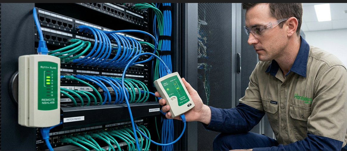
- Patch panel verification
- Fibre identification in crowded racks
- Quick fault isolation
- Post-installation QA checks
Field Insight:
Many technicians use VFL before OTDR testing to quickly eliminate obvious faults and reduce diagnostic time.
Types of Visual Fault Locators
1. Standard VFL (2–10 mW)
- Most common type
- Suitable for patch leads and short runs
- USB or battery powered
2. High-power VFL (10–30 mW)
- Greater visibility through jackets
- Used for longer fibre runs
- More effective in outdoor cables
3. Pen-style VFL
- Compact and portable
- Ideal for quick checks in tight racks
- Lower power output
Most enterprise technicians will find a 10 mW rechargeable VFL provides the best balance of visibility, battery life and portability.
How to Use a VFL (Step-by-Step)
Step 1: Safety check
Ensure fibre is disconnected from active equipment.
Step 2: Clean connectors
Dirty connectors can mask or distort faults. Before testing, inspect the connector using a Fibre Optic Inspection Microscope and clean it with a One-Click Fibre Cleaner. Contaminated connectors are responsible for a large percentage of field faults.
Fibre cleaning products are essential here:
Step 3: Connect VFL to fibre
Attach using:
- LC
- SC
- Universal 2.5 mm or 1.25 mm adapters
Step 4: Activate laser
Turn on continuous or flashing mode.
Step 5: Inspect fibre path
Look for:
- Bright red leaks (faults)
- Weak glow (attenuation points)
- No light (break or disconnection)
Step 6: Trace and isolate
Follow the fibre along the route to pinpoint the issue.
Common Fault Signatures
Full break
- Bright red light escaping clearly
- Easy to locate
Severe bend
- Arc-shaped glow
- Intensity varies with bend angle
Dirty connector
- Weak or flickering glow
- Often intermittent
Wrong patching
- No light at expected endpoint
- Light appears in incorrect port
VFL Limitations
While extremely useful, VFLs have limitations:
- Limited range (best under ~5–10 km depending on fibre and power)
- Cannot measure loss in dB
- Cannot detect micro-defects
- Not suitable for deep network analysis
- Less effective on dark jacketed or armored cable
For full diagnostics, use OTDR testing event table explained:
Safety Considerations
Even though VFLs use visible light, they are still laser devices.
Safety rules:
- Never point into eyes
- Avoid direct viewing of fibre ends
- Use proper connectors before activation
- Follow IEC laser safety guidelines
Reference University of Wollongong:
IEC 60825-1 (Laser safety classification)
VFL in Real-World Fibre Installations
Case: Mispatched fibre in data centre rack
Problem:
- Link not coming up
- OTDR not yet deployed
Action:
Technician used VFL on patch panel.
Result:
- Light traced to incorrect port
- Fibre was cross-connected during patching
Outcome:
Issue resolved in under 5 minutes without OTDR testing.
Case: Underground break during civil works
Problem:
- Complete signal loss on link
Action:
VFL injected from nearest accessible joint.
Result:
- Bright red glow visible at trench location
Outcome:
Fault location pinpointed before excavation.
Engineering Tips for VFL Use
- Always start fault diagnosis with VFL before OTDR
- Use flashing mode in bright environments
- Combine with inspection microscope for connector issues
- Label fibres immediately after identification
- Keep spare adapters for LC/SC/ST connectors
We’ve found technicians often blame a splice when the real problem is a contaminated connector. Always inspect and clean before re-splicing.
Common Mistakes in the Field
1. Using VFL on live fibre systems
Can damage equipment or create inaccurate results.
2. Skipping cleaning before testing
Dust can block or distort visible light.
3. Misinterpreting weak glow as “no fault”
Weak light often indicates partial attenuation or poor splice quality.
4. Relying solely on VFL for long-distance faults
Beyond short distances, OTDR is required.
FibreSales Product Integration (Shop-First Approach)
A reliable VFL workflow depends on supporting infrastructure products:
Fibre Inspection & Cleaning Tools
Essential before any VFL test to ensure accurate visibility.
Shop cleaning kits:
Patch Leads & Adapters
Correct adapters ensure proper coupling to fibre types.
Browse patch leads:
Fibre Testing Ecosystem
VFL is part of a broader testing workflow including OTDR and power meters.
Test equipment accessories:
Quick Reference Table
| Scenario | Use VFL? | Better Tool |
|---|---|---|
| Fibre break location | Yes | OTDR (confirm) |
| Continuity check | Yes | None needed |
| Loss measurement | No | Power meter |
| Network commissioning | Yes (initial) | OTDR + OLTS |
| Long-haul fault finding | Limited | OTDR |
FAQ
What does a VFL detect?
Breaks, bends, faulty connectors, and continuity issues in fibre optic cables.
How far can a VFL work?
Typically up to 5–10 km depending on fibre type and conditions.
Can a VFL damage fibre?
No, but it can damage eyes if misused.
Is VFL enough for certification?
No. It is a diagnostic tool, not a certification instrument.
Conclusion
A Visual Fault Locator is one of the most efficient first-response tools in fibre optic fault diagnosis. While it does not replace OTDR or power meter testing, it dramatically speeds up troubleshooting by making invisible fibre faults visible in real time.
For field technicians, mastering VFL usage means faster installs, quicker fault isolation, and fewer unnecessary escalations. Over the years we’ve found that nearly every technician carries a VFL, yet many overlook its value after termination. In reality, it can save significant troubleshooting time by confirming continuity before more advanced testing begins.
For professional OTDRs , Power Meters, Light Sources, Cleaning Products and Inspection Microscopes, visit www.fibresales.com.au to explore Australia’s growing resource centre for fibre optic products, technical guides and professional testing solutions.