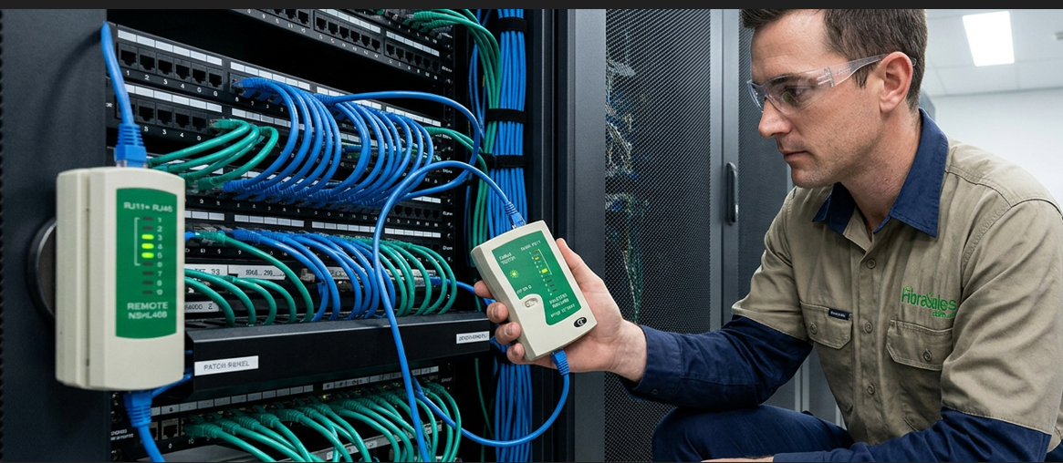
RJ45 Pinout Guide: T568A vs T568B Wiring Diagrams Explained
Introduction
RJ45 Pinout is one of the most searched networking topics because every Ethernet connection depends on the correct arrangement of eight conductors inside an RJ45 connector. Whether you’re installing a home network, expanding an office, fitting out a data centre or terminating structured cabling, using the correct pinout ensures reliable communication between network devices.
Although many installers refer to “RJ45 wiring”, the wiring standard itself has remained unchanged across Cat5e, Cat6 and Cat6A Ethernet cabling. The differences between cable categories come from conductor design, pair separation, shielding and manufacturing quality—not from the order of the wires inside the connector.
Understanding the two recognised wiring standards, T568A and T568B, helps prevent common problems such as failed links, reduced network speeds, Power over Ethernet (PoE) faults and intermittent connectivity.
This guide explains:
- What an RJ45 pinout is.
- The differences between T568A and T568B.
- Complete RJ45 wiring diagrams.
- RJ45 colour codes.
- How to terminate Ethernet cables correctly.
- Common installation mistakes.
- RJ45 troubleshooting.
- Gigabit and 10 Gigabit Ethernet considerations.
- Industry standards and best practices.
For many installations, terminating your own Ethernet cables is the right solution. However, where reliability, certification and long-term performance are important, professionally manufactured Cat6 Patch Cables provide factory-tested performance and eliminate many of the faults associated with field-terminated patch leads.
What Is an RJ45 Pinout?
An RJ45 pinout defines the exact position of each conductor inside an RJ45 connector. It specifies how the eight individual wires within an Ethernet cable terminate onto the eight contacts of an 8P8C (Eight Position, Eight Contact) modular connector.
This wiring arrangement allows Ethernet devices such as:
- Computers
- Network switches
- Routers
- Wireless access points
- IP phones
- Security cameras
- Network storage devices
to exchange data reliably across a Local Area Network (LAN).
The purpose of a standardised pinout is simple: every Ethernet device expects each twisted pair to appear on specific connector pins. When every cable follows the same recognised standard, equipment from different manufacturers remains fully compatible.
Today, two internationally recognised pinout standards are used throughout structured cabling systems:
- T568A
- T568B
Both standards provide identical electrical performance. The only difference is the position of the green and orange wire pairs.
Why Correct RJ45 Wiring Matters
Correct termination affects far more than basic connectivity.
Poorly terminated connectors can cause:
- Links negotiating at 100 Mbps instead of 1 Gbps.
- Failed 10 Gigabit Ethernet connections.
- Packet loss.
- High crosstalk.
- Increased return loss.
- Intermittent network faults.
- PoE devices failing to power correctly.
- Costly troubleshooting after installation.
Maintaining the correct wire order, preserving the twist of each conductor pair and using quality connectors all contribute to signal integrity throughout the network.
This becomes increasingly important as network speeds continue to increase. While older Fast Ethernet systems only used two wire pairs, modern Gigabit Ethernet and 10 Gigabit Ethernet utilise all four twisted pairs, making correct termination essential for maximum performance.
Engineering Decision
Many organisations still hand-crimp patch leads during installation. While this is suitable for custom cable lengths and specialised applications, factory-manufactured patch leads generally provide greater consistency because every cable is machine terminated and tested before shipment. For switch connections, patch panels and equipment racks, professionally manufactured Cat6 Patch Cables are often the preferred choice for reducing installation time and improving long-term reliability.
T568A vs T568B: Which RJ45 Pinout Should You Use?
Every Ethernet cable terminated with an RJ45 connector uses one of two recognised wiring standards:
- T568A
- T568B
Both standards are defined within the ANSI/TIA-568 structured cabling standard and provide identical electrical performance. Neither is faster than the other, and neither offers better bandwidth or improved signal quality. The only difference is the position of the orange and green wire pairs within the connector.
As long as both ends of a straight-through Ethernet cable use the same wiring standard, network performance remains exactly the same.
For new installations in Australia, T568B is the most commonly used standard because it aligns with the majority of commercially manufactured Ethernet patch cables and existing structured cabling systems. However, if an existing installation has been wired using T568A, it is best practice to continue using that standard throughout the network to maintain consistency.
The most important rule is simple:
Choose one standard and use it consistently throughout the installation.
Mixing standards unintentionally can create unnecessary troubleshooting and compatibility issues.
T568A RJ45 Pinout
T568A places the green pair before the orange pair while maintaining the same four twisted pairs used by every Ethernet cable.
| Pin | Wire Colour | Pair |
|---|---|---|
| 1 | White/Green | Pair 3 |
| 2 | Green | Pair 3 |
| 3 | White/Orange | Pair 2 |
| 4 | Blue | Pair 1 |
| 5 | White/Blue | Pair 1 |
| 6 | Orange | Pair 2 |
| 7 | White/Brown | Pair 4 |
| 8 | Brown | Pair 4 |
Typical Applications
T568A is commonly used for:
- Residential structured cabling
- Government installations where specified
- Networks matching existing T568A infrastructure
- Legacy structured cabling systems
Although less common in Australian commercial installations, T568A remains a fully compliant Ethernet wiring standard.
T568B RJ45 Pinout
T568B swaps the position of the orange and green pairs while leaving every other conductor unchanged.
| Pin | Wire Colour | Pair |
|---|---|---|
| 1 | White/Orange | Pair 2 |
| 2 | Orange | Pair 2 |
| 3 | White/Green | Pair 3 |
| 4 | Blue | Pair 1 |
| 5 | White/Blue | Pair 1 |
| 6 | Green | Pair 3 |
| 7 | White/Brown | Pair 4 |
| 8 | Brown | Pair 4 |
Typical Applications
T568B is widely used for:
- Commercial offices
- Schools
- Universities
- Hospitals
- Data centres
- Industrial facilities
- Enterprise networks
It is also the wiring sequence used by most factory-manufactured Cat6 Patch Cables, making it the preferred choice for many Australian installers.
T568A vs T568B Comparison
| Feature | T568A | T568B |
|---|---|---|
| Electrical Performance | Identical | Identical |
| Supports Gigabit Ethernet | Yes | Yes |
| Supports 10 Gigabit Ethernet | Yes | Yes |
| Supports PoE | Yes | Yes |
| ANSI/TIA Compliant | Yes | Yes |
| Common in Australian Commercial Networks | Less Common | Most Common |
| Common on Factory Patch Leads | Less Common | Yes |
There is no performance advantage to choosing one standard over the other. Network speed is determined by factors such as:
- Cable category
- Connector quality
- Installation practices
- Link length
- Shielding (where required)
- Compliance with structured cabling standards
The wiring sequence itself has no effect on bandwidth.
Why Consistency Is More Important Than the Standard
One of the most common installation mistakes is assuming that T568A and T568B can be mixed without consequence.
While both standards work perfectly, they must be applied consistently across the cabling system.
Changing between standards at random creates unnecessary confusion during future maintenance, fault finding and network expansion. Labelling may no longer match physical wiring, making it more difficult for technicians to diagnose problems.
Professional installers typically select one standard during the design stage and apply it to:
- Patch panels
- Keystone jacks
- Wall outlets
- Patch leads
- Equipment cabinets
- Telecommunications rooms
This approach ensures every cable follows the same documented wiring practice.
Engineering Decision
If you’re installing a new network with no existing cabling to match, T568B is generally the preferred choice for Australian commercial environments because it aligns with the majority of factory-manufactured Ethernet patch leads and existing structured cabling installations.
If you’re extending or repairing an existing network, always match the wiring standard already in use. Maintaining consistency is far more important than changing standards midway through an installation.
What’s Next?
Now that you understand the differences between T568A and T568B, the next step is learning how each wire is arranged inside the connector.
RJ45 Wiring Diagram and Colour Codes
Once you’ve selected either T568A or T568B, the next step is understanding how the eight conductors are arranged inside the RJ45 connector. Although the wire colours appear straightforward, each conductor forms part of a balanced twisted pair designed to minimise electromagnetic interference (EMI), reduce crosstalk and maintain signal integrity.
A common mistake made by first-time installers is treating each wire individually. In reality, Ethernet is designed around four twisted wire pairs, not eight separate conductors. Keeping these pairs together as close as possible to the connector is one of the most important factors in achieving reliable network performance.
RJ45 Connector Pin Numbering
When viewing an RJ45 connector from the front with the gold contacts facing towards you and the retaining clip facing away, the pins are numbered from left to right.
 -----------------------------------------
| 1 | 2 | 3 | 4 | 5 | 6 | 7 | 8 |
 -----------------------------------------
Maintaining the correct pin numbering is essential when following either the T568A or T568B wiring sequence.
T568B Colour Code
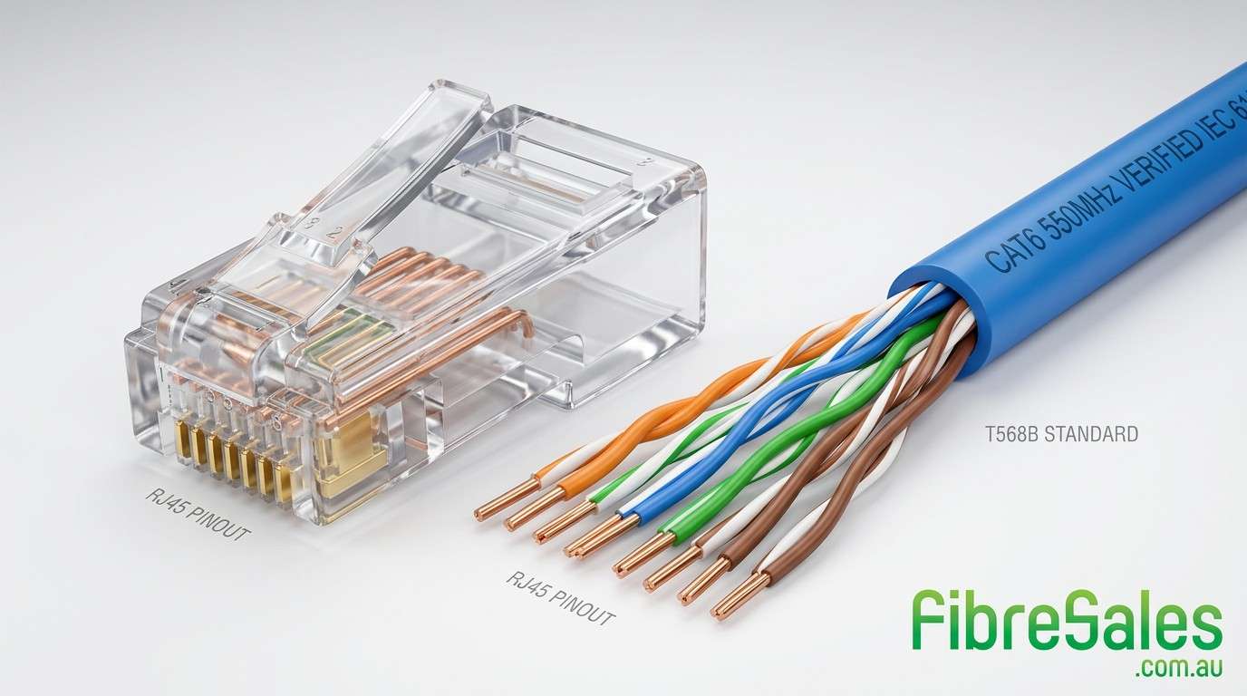
T568B is the most widely used wiring standard in Australian commercial networks.
| Pin | Wire Colour | Twisted Pair |
|---|---|---|
| 1 | White/Orange | Pair 2 |
| 2 | Orange | Pair 2 |
| 3 | White/Green | Pair 3 |
| 4 | Blue | Pair 1 |
| 5 | White/Blue | Pair 1 |
| 6 | Green | Pair 3 |
| 7 | White/Brown | Pair 4 |
| 8 | Brown | Pair 4 |
T568B Wire Sequence
- White/Orange
- Orange
- White/Green
- Blue
- White/Blue
- Green
- White/Brown
- Brown
This is the sequence used on most commercially manufactured Ethernet patch leads.
T568A Colour Code
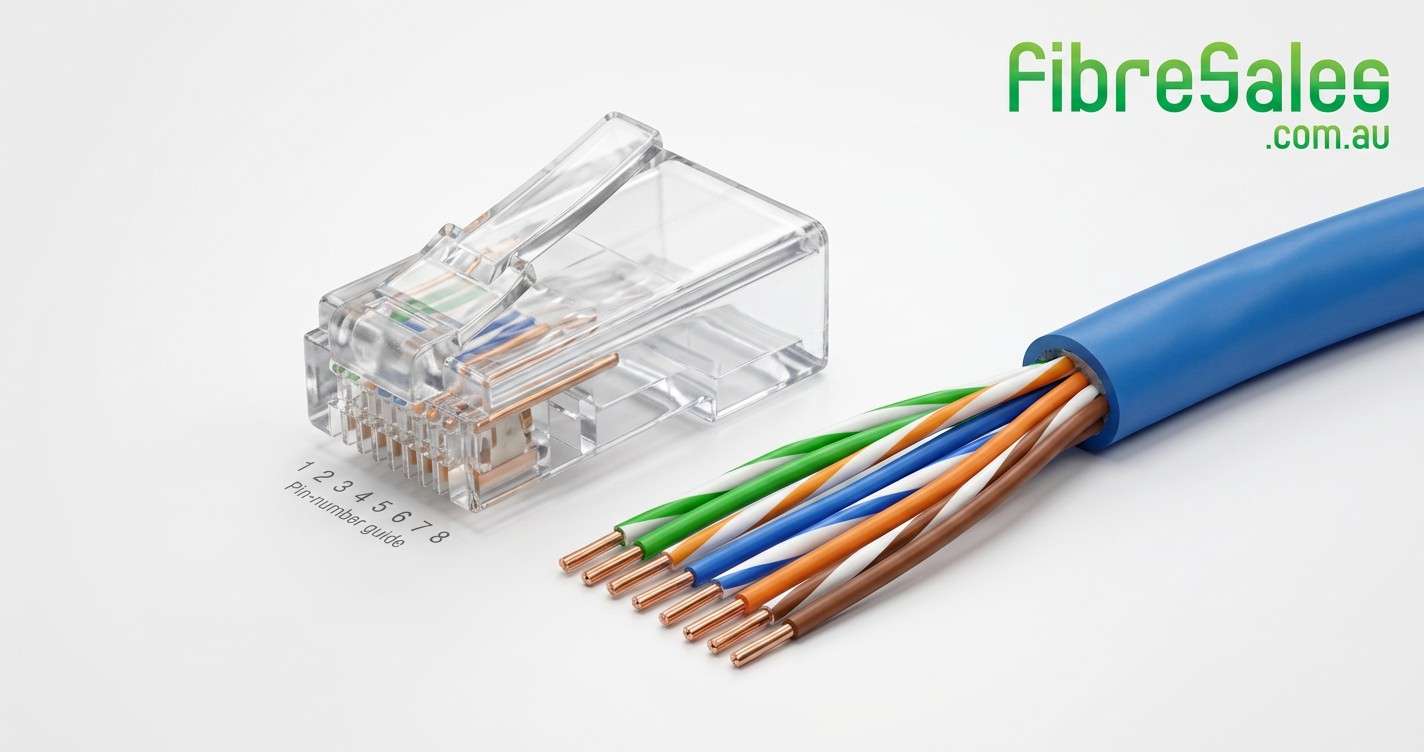
Although less common in commercial installations, T568A is equally compliant with structured cabling standards.
| Pin | Wire Colour | Twisted Pair |
|---|---|---|
| 1 | White/Green | Pair 3 |
| 2 | Green | Pair 3 |
| 3 | White/Orange | Pair 2 |
| 4 | Blue | Pair 1 |
| 5 | White/Blue | Pair 1 |
| 6 | Orange | Pair 2 |
| 7 | White/Brown | Pair 4 |
| 8 | Brown | Pair 4 |
T568A Wire Sequence
- White/Green
- Green
- White/Orange
- Blue
- White/Blue
- Orange
- White/Brown
- Brown
Notice that only the green and orange pairs change position. The blue and brown pairs remain identical in both standards.
Why Ethernet Uses Twisted Pairs
Ethernet cables contain four balanced twisted pairs rather than eight straight conductors because twisting significantly reduces interference from nearby electrical equipment and neighbouring cable pairs.
Each pair carries equal and opposite electrical signals. External noise affects both conductors almost equally, allowing the receiving equipment to reject unwanted interference through a process known as common-mode noise rejection.
Maintaining the twist right up to the connector is therefore critical.
Excessively untwisting the conductors during termination increases:
- Near-End Crosstalk (NEXT)
- Alien Crosstalk (AXT)
- Return Loss
- Signal reflections
- Transmission errors
These problems become increasingly important on high-speed networks operating at 2.5 Gigabit, 5 Gigabit and 10 Gigabit Ethernet.
Does Cat6 Use a Different Pinout?
One of the most common questions asked by installers is whether Cat6 requires a different RJ45 pinout from Cat5e.
The answer is no.
Every recognised twisted-pair Ethernet cable category uses exactly the same wiring sequence.
| Cable Category | T568A | T568B |
|---|---|---|
| Cat5e | ✔ | ✔ |
| Cat6 | ✔ | ✔ |
| Cat6A | ✔ | ✔ |
The differences between cable categories come from the cable’s physical construction rather than its wiring order.
For example:
| Feature | Cat5e | Cat6 | Cat6A |
|---|---|---|---|
| Operating Frequency | 100 MHz | 250 MHz | 500 MHz |
| Typical 10G Support | Limited | Up to 55 m* | Up to 100 m |
| Conductor Size | Smaller | Larger | Larger |
| Pair Separation | Standard | Improved | Improved |
| Shielding Options | Available | Available | Common |
*Actual performance depends on installation quality and environmental conditions.
This means installers only need to learn one wiring method, regardless of whether they’re terminating Cat5e, Cat6 or Cat6A Ethernet cable.
Why Connector Selection Matters
Although the pinout remains identical across cable categories, the connector itself must match the cable being terminated.
Cat6 and Cat6A cables typically have:
- Thicker conductors
- Larger overall cable diameter
- Higher-performance insulation
- Internal pair separator (spline) on many designs
Using connectors designed for smaller Cat5e conductors can make it difficult to insert the wires correctly and may result in poor contact between the conductors and the connector pins.
For reliable performance, always match:
- Cable category
- Connector category
- Termination tool
Using components designed to work together helps maintain compliance with structured cabling standards and reduces the likelihood of installation faults.
Engineering Decision
Although field termination is sometimes necessary, every manual crimp introduces another opportunity for installation error. In commercial environments where multiple patch leads are required, professionally manufactured Cat6 Patch Cables provide consistent conductor spacing, factory-controlled termination and individual testing before shipment. This reduces installation time while improving long-term network reliability.
How to Wire an RJ45 Connector Step-by-Step
Once you’ve selected your wiring standard and understand the RJ45 colour codes, the next stage is terminating the connector correctly.
Although the process is relatively straightforward, small mistakes during preparation or crimping can significantly affect network performance. Poor terminations are a common cause of intermittent faults, reduced Ethernet speeds and failed Power over Ethernet (PoE) devices.
The objective is not simply to make all eight wires fit inside the connector. A quality termination maintains the cable’s electrical characteristics while creating a secure mechanical connection that will remain reliable for years.
Tools You’ll Need
Using the correct tools makes the installation faster, easier and more reliable.
For most RJ45 terminations you’ll need:
- RJ45 crimping tools
- Wire stripper
- Cable cutter or flush cutters
- Cat6-rated RJ45 connectors
- Ethernet cable (Cat5e, Cat6 or Cat6A)
- RJ45 cable tester
If you’re terminating permanent structured cabling rather than making patch leads, you’ll also require:
- Keystone jack
- Punch-down tool
- Cable management accessories
- Cable labels
Using quality tools helps produce more consistent terminations while reducing the likelihood of damaging conductors during installation.
Step 1 – Measure and Cut the Cable
Measure the required cable length before making any cuts.
Where possible, allow a small amount of additional length for future equipment movement or maintenance. Avoid pulling the cable tightly between devices, as tension can place unnecessary strain on both the cable and the connector.
Use a quality cable cutter to produce a clean, square cut.
Avoid crushing the cable while cutting, as this may distort the conductors and make termination more difficult.
Step 2 – Strip the Outer Jacket
Remove approximately 25–30 mm of the outer jacket using a wire stripper.
Take care not to nick or damage the insulation surrounding the individual conductors.
If your cable contains:
- Rip cord
- Central spline
- Separator
- Shield drain wire
trim these components neatly without damaging the twisted pairs.
A clean preparation makes the remaining steps considerably easier.
Step 3 – Untwist the Pairs Carefully
Separate the four twisted pairs.
Straighten each conductor only as much as necessary.
One of the biggest mistakes made during RJ45 termination is untwisting excessive lengths of cable.
Ideally, the twist should remain intact until within approximately 13 mm (½ inch) of the connector.
Maintaining the twists helps preserve:
- Signal integrity
- Crosstalk performance
- Return loss
- Gigabit Ethernet performance
- 10 Gigabit Ethernet performance
Step 4 – Arrange the Wires
Select either the T568A or T568B sequence.
Arrange the conductors in the correct order while keeping them flat and parallel.
Double-check the colour sequence before continuing.
Many installers pause briefly at this stage because correcting the order now is much easier than replacing a connector after crimping.
Step 5 – Trim the Conductors
Once aligned, trim the conductors to approximately 12–13 mm.
All eight conductors should finish at exactly the same length.
Uneven conductors may fail to reach the front of the connector, preventing the contact pins from piercing the insulation correctly.
A clean, even cut also makes inserting the cable considerably easier.
Step 6 – Insert the RJ45 Connector
Carefully slide the conductors into the connector while maintaining their correct sequence.
Before crimping, verify that:
- Every conductor reaches the front of the connector.
- The wire order remains correct.
- The cable jacket extends inside the connector.
- The strain relief will clamp onto the outer jacket rather than the individual conductors.
This final inspection takes only a few seconds but prevents many common termination failures.
Step 7 – Crimp the Connector
Insert the connector fully into the crimping tool.
Apply firm, even pressure until the tool completes its full cycle.
During crimping:
- The metal contacts pierce each conductor.
- The strain relief secures the cable jacket.
- The connector locks permanently onto the cable.
Avoid partially crimping the connector or releasing the tool before the cycle is complete.
Step 8 – Repeat the Second End
If you’re creating a standard Ethernet patch cable, terminate the opposite end using exactly the same wiring standard.
| Cable Type | End A | End B |
|---|---|---|
| Straight-through | T568B | T568B |
| Straight-through | T568A | T568A |
| Crossover | T568A | T568B |
Modern switches and network equipment generally support Auto MDI-X, meaning crossover cables are rarely required today. However, understanding the difference remains useful when working with legacy equipment or specialised network hardware.
Step 9 – Test the Cable
Testing should always be the final stage of installation.
Even experienced installers occasionally encounter:
- Reversed conductors
- Open circuits
- Short circuits
- Split pairs
- Poor crimps
A cable tester confirms that all eight conductors are correctly terminated before the cable is placed into service.
Testing every cable during installation is considerably faster than fault-finding after equipment has been connected.
Common Termination Mistakes
Most RJ45 faults result from a handful of avoidable mistakes.
Mixing T568A and T568B
Using different wiring standards at each end unintentionally creates a crossover cable.
Unless specifically required, both ends should use the same wiring standard.
Untwisting Too Much Cable
Removing excessive twist from the conductor pairs reduces the cable’s ability to reject interference.
Always maintain the twists as close to the connector as possible.
Using the Wrong Connector
Cat6 cable should be terminated using connectors designed for Cat6 conductors.
Attempting to terminate larger conductors inside Cat5e connectors can lead to unreliable contact and poor mechanical retention.
Failing to Seat the Cable Jacket
The connector’s strain relief should grip the outer cable jacket—not the individual conductors.
If only the conductors are secured, repeated movement may eventually break the connection.
Skipping Cable Testing
Assuming a cable works because it “looks right” often leads to unnecessary troubleshooting later.
A cable tester verifies the termination before the cable is installed into production.
Engineering Decision
While terminating RJ45 connectors is an essential skill for installers and technicians, it is not always the most efficient solution.
For switch-to-switch connections, patch panels, servers and network equipment, professionally manufactured Cat6 Patch Cables offer several advantages:
- Factory-controlled termination
- Individual performance testing
- Consistent conductor alignment
- Reduced installation time
- Improved long-term reliability
- Available in multiple colours and lengths for organised cable management
Custom terminations remain valuable where non-standard cable lengths are required, but for the majority of equipment interconnections, factory-tested patch leads provide a faster and more consistent solution.
RJ45 Troubleshooting, Advanced Wiring and Installation Best Practices
Even when an RJ45 connector is terminated correctly, network problems can still occur if the cable has been damaged, the connector is incompatible with the cable, or the installation doesn’t follow recognised industry standards. Fortunately, most Ethernet faults follow predictable patterns, making them relatively straightforward to diagnose with a systematic approach.
Rather than replacing switches, routers or computers first, always begin by checking the physical layer. A correctly terminated cable that complies with the IEEE 802.3 Ethernet Standard and the ANSI/TIA-568 Structured Cabling Standard provides the foundation for reliable network performance.
Why Is My Ethernet Connection Only Running at 100 Mbps?
One of the most common networking issues is a Gigabit device connecting at only 100 Mbps.
While this often appears to be a switch or network card problem, the cause is usually the cable itself.
Unlike Fast Ethernet, Gigabit Ethernet uses all four twisted pairs. If one conductor fails to make proper contact or one pair has been incorrectly terminated, the network interface will often negotiate down to 100 Mbps to maintain communication.
Common causes include:
- Incorrect RJ45 pinout.
- Split wire pairs.
- Poorly crimped connector.
- Damaged conductors.
- Low-quality RJ45 connectors.
- Using connectors not designed for Cat6 cable.
- Excessive untwisting during termination.
Testing the cable before replacing network hardware can save considerable troubleshooting time.
Common RJ45 Wiring Problems
The table below summarises the most frequently encountered Ethernet cabling faults and their likely causes.
| Symptom | Possible Cause | Recommended Action |
|---|---|---|
| No network connection | Incorrect wire order | Check the T568A or T568B pin sequence and re-terminate if required. |
| Connection limited to 100 Mbps | Open conductor or split pair | Test all eight conductors using an Ethernet cable tester. |
| Intermittent network connection | Poor crimp or damaged connector | Replace the RJ45 connector and retest. |
| Packet loss | Excessive untwisting or cable damage | Re-terminate while maintaining pair twists close to the connector. |
| PoE device will not power on | Incorrect termination or damaged conductor | Verify continuity across all eight conductors. |
| Frequent link drops | Poor-quality components | Replace with quality Cat6-rated connectors or factory-tested Cat6 Patch Cables. |
Working methodically through these checks will resolve the majority of Ethernet cabling faults without unnecessary equipment replacement.
RJ45 Pinouts and Power over Ethernet (PoE)
Power over Ethernet (PoE) allows both electrical power and network data to be transmitted over the same Ethernet cable. This technology is defined by the IEEE 802.3 Power over Ethernet Standard and is widely used for:
- Wireless access points
- IP security cameras
- VoIP telephones
- Access control systems
- Building automation devices
- Industrial Ethernet equipment
Because PoE relies on correct conductor continuity, a poorly terminated RJ45 connector may still pass data while failing to deliver reliable power.
When installing PoE networks:
- Use Cat6-rated connectors with Cat6 cable.
- Maintain the twist of each wire pair until the connector.
- Avoid crushing or excessively bending the cable.
- Test every completed cable before deployment.
Where multiple PoE devices are installed, professionally manufactured Cat6 Patch Cables help ensure consistent performance and reduce installation time.
Advanced RJ45 Wiring Configurations
Most Ethernet networks use straight-through cables. However, technicians occasionally encounter other wiring configurations when working with legacy equipment or performing diagnostics.
Straight-Through Cable
A straight-through cable uses the same wiring standard at both ends.
Examples include:
- T568B to T568B
- T568A to T568A
This is the standard configuration for connecting:
- Computers to switches
- Switches to routers
- Patch panels to switches
- Servers to network infrastructure
- Wireless access points
Nearly all commercially manufactured Cat6 Patch Cables use this configuration.
Crossover Cable
A crossover cable uses T568A on one end and T568B on the other.
Historically, crossover cables were used to connect:
- Computer to computer
- Switch to switch
- Hub to hub
Most modern network equipment supports Auto MDI-X, meaning crossover cables are now rarely required. However, understanding their purpose remains useful when working with older networking hardware.
Rollover Cable
A rollover cable is used for console access rather than Ethernet communication.
Unlike straight-through or crossover cables, every pin is reversed, making rollover cables suitable for configuring routers, switches and other network devices through their console ports.
Loopback Cable
Loopback cables are specialised diagnostic tools used to test network interfaces and communication paths.
By routing transmitted signals back to the receiving pins, technicians can verify:
- Network interface cards (NICs)
- Switch ports
- Cable testers
- Network diagnostic equipment
Although rarely used outside technical environments, loopback cables remain valuable for fault diagnosis.
Best Practice Installation Tips
Following recognised installation practices helps maximise network performance while reducing future maintenance.
The ANSI/TIA-568 Structured Cabling Standard, ISO/IEC 11801 Generic Cabling Standard and the BICSI Telecommunications Distribution Methods Manual (TDMM) all recommend maintaining cable integrity throughout installation.
Best practices include:
- Maintain the recommended minimum bend radius.
- Avoid pulling Ethernet cables with excessive force.
- Keep network cabling separated from mains electrical wiring where practical.
- Label both ends of every cable.
- Use cable management to reduce strain on connectors.
- Protect connectors from contamination during installation.
- Test every cable before placing it into service.
For permanent telecommunications cabling in Australia, installers should also comply with the ACMA Cabling Standards.
Engineering Decision
Learning to terminate RJ45 connectors is a valuable skill, particularly when custom cable lengths are required. However, for switch cabinets, communications racks, office fit-outs and data centres, factory-manufactured Cat6 Patch Cables generally provide the best combination of performance, consistency and installation efficiency.
Each cable is manufactured under controlled conditions and tested before shipment, helping to reduce installation faults while supporting reliable Gigabit and 10 Gigabit Ethernet performance.
Where custom lengths are unnecessary, choosing professionally manufactured patch leads can significantly reduce installation time and improve long-term network reliability.
Frequently Asked Questions
What is an RJ45 pinout?
An RJ45 pinout is the recognised arrangement of the eight conductors inside an RJ45 (8P8C) connector. It defines the position of each wire according to either the T568A or T568B wiring standard, ensuring Ethernet devices communicate reliably across a network.
Is T568A better than T568B?
No. Both wiring standards provide identical electrical performance and support the same Ethernet speeds. The ANSI/TIA-568 Structured Cabling Standard recognises both standards. The important requirement is to use the same standard consistently throughout the installation.
Which RJ45 wiring standard is most common in Australia?
T568B is the most widely used wiring standard for Australian commercial and business networks because it matches the majority of factory-manufactured Ethernet patch leads and existing structured cabling installations.
Can I use the same RJ45 pinout for Cat5e, Cat6 and Cat6A?
Yes. The RJ45 pinout remains exactly the same across Cat5e, Cat6 and Cat6A cables.
The performance differences between cable categories are determined by cable construction, conductor size, shielding and manufacturing quality—not by the wiring sequence.
Does an incorrect RJ45 pinout affect network speed?
Yes.
Incorrect wiring can cause:
- Reduced network speeds
- Failed Gigabit Ethernet links
- Packet loss
- Power over Ethernet (PoE) faults
- Intermittent connectivity
Testing every completed cable helps identify wiring faults before deployment.
Why is my Ethernet connection only negotiating at 100 Mbps?
A Gigabit Ethernet connection requires all eight conductors to operate correctly.
Common causes include:
- Incorrect RJ45 wiring
- Damaged conductors
- Poor crimps
- Split wire pairs
- Damaged connectors
Testing the cable should always be the first troubleshooting step.
Can I make my own Ethernet patch leads?
Yes. Field termination is appropriate when custom cable lengths are required or when repairing existing cabling.
However, for communications cabinets, offices, schools and data centres, factory-tested Cat6 Patch Cables generally provide better consistency, reduced installation time and improved long-term reliability.
Do I need special RJ45 connectors for Cat6 cable?
Yes.
Cat6 cable typically uses larger conductors than Cat5e and often includes an internal separator. Using Cat6-rated RJ45 connectors helps ensure correct conductor alignment and reliable termination.
What tools are required to terminate an RJ45 connector?
The essential tools include:
- RJ45 crimping tool
- Wire stripper
- Cable cutter
- Cat6-rated RJ45 connectors
- Ethernet cable tester
For structured cabling installations, a punch-down tool may also be required when terminating keystone jacks or patch panels.
What standards apply to RJ45 wiring?
Professional Ethernet installations commonly follow:
- ANSI/TIA-568 Structured Cabling Standard
- IEEE 802.3 Ethernet Standard
- ISO/IEC 11801 Generic Cabling Standard
- BICSI Telecommunications Distribution Methods Manual (TDMM)
Australian installations should also comply with the ACMA Cabling Standards where applicable.
Why Choose fibreSales?
- Australian stock
- Fast dispatch
- Technical support
- Installer-focused product range
- Trusted by IT professionals, contractors and data centres
Whether you’re building a small office network or deploying structured cabling across a large commercial facility, choosing quality networking products helps reduce installation time and improve long-term reliability.
At fibreSales, we supply networking professionals, electrical contractors, IT departments, telecommunications installers and data centre operators throughout Australia with trusted networking products backed by technical expertise.
Our range includes:
- Cat6 Patch Cables
- Fibre optic patch leads
- SFP and SFP+ transceivers
- Fibre optic cleaning products
- Test equipment
- Installation tools
Whether you need a single Ethernet patch lead or complete network infrastructure products, our team can help you choose the right solution for your application.
Related Products
You may also be interested in:
Conclusion
Understanding the correct RJ45 Pinout is fundamental to building reliable Ethernet networks. While the T568A and T568B wiring standards differ only in the position of the green and orange wire pairs, consistent application of one standard throughout an installation is essential for dependable network performance.
Correct termination practices, quality connectors and compliance with recognised industry standards all contribute to reliable Gigabit Ethernet, 10 Gigabit Ethernet and Power over Ethernet (PoE) operation. Equally important is testing every completed cable before it is placed into service, helping identify faults before they become costly network problems.
For many installations, terminating custom Ethernet cables remains an essential skill. However, where standard lengths are suitable, professionally manufactured Cat6 Patch Cables provide factory-tested quality, consistent performance and faster installation.
For more fibre optic solutions, technical resources, and installation products, visit www.fibresales.com.au.
Continue Learning
Expand your networking knowledge with these related fibreSales resources:
- Copper Networking Explained | The Complete Guide to Ethernet Networks
- Copper Patch Leads Explained | The Complete Guide to Ethernet Patch Cables
- Can Cat6 Run 10G?
- UTP vs Shielded Cat6 Patch Cables | Which Should You Choose?
- LSZH vs PVC Cat6 Patch Cables | Which Jacket Should You Choose?
- Do Cat6 Patch Lead Colours Matter?
- RJ45 Connectors Explained
- What does RJ45 Mean
- Why Most Ethernet Networks Use T568B