Fibre Installation Best Practices
INTRODUCTION
Fibre installation best practices are essential for building reliable, high-performance optical networks. Even high-quality fibre components can fail if installation techniques are not correctly applied.
In real-world deployments, most fibre faults are caused by installation errors such as poor routing, contamination, or excessive bend stress rather than material defects.
This guide outlines the key practices used by experienced technicians to ensure long-term network stability.
1. BEND RADIUS CONTROL (CRITICAL)
Maintaining correct bend radius is one of the most important installation rules in fibre networks.
Rmin≥10–20×DR_{min} \geq 10\text{–}20 \times D
Where D is the cable diameter.
Why it matters:
- Prevents micro-bending loss
- Avoids long-term signal degradation
- Reduces physical fibre stress
Related guide:
https://fibresales.com.au/bend-radius-the-unseen-problem/
2. CLEANLINESS BEFORE CONNECTION (TOP FAILURE CAUSE)
Contamination is one of the leading causes of fibre network failure.
In field environments, even microscopic dust particles can significantly increase insertion loss and cause intermittent link failures.
Best practice:
- Inspect before every connection
- Clean before mating connectors
- Never assume a connector is clean
https://fibresales.com.au/fibre-optic-cleaning/
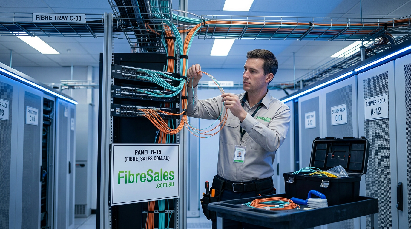
3. CORRECT CABLE ROUTING
Proper routing ensures fibre longevity and reduces mechanical stress.
Avoid:
- Sharp edges
- Tight cable trays
- Power cable interference
- Vibration zones
Recommended:
- Smooth tray transitions
- Structured separation from electrical cables
- Controlled slack management
4. LABELLING AND DOCUMENTATION
Good documentation reduces troubleshooting time and improves maintenance efficiency.
Includes:
- Fibre ID labelling
- Patch panel mapping
- Splice tray documentation
- Route diagrams
In large installations, poor documentation is one of the biggest causes of delayed fault resolution.
5. SPLICING AND TERMINATION CONTROL
Splicing and termination quality directly impacts network performance.
Key risks:
- Misalignment during fusion splicing
- Contamination during termination
- Incorrect stripping lengths
Related:
https://fibresales.com.au/fibre-optic-splicing-installation-guide/
6. COMMON INSTALLATION MISTAKES
Most fibre failures are not material failures — they are installation errors.
Common issues:
- Exceeding bend radius limits
- Dirty connectors during termination
- Incorrect polarity in MPO systems
- Poorly secured enclosures
- Improper splice protection
7. ENVIRONMENTAL CONSIDERATIONS
Fibre behaves differently depending on installation environment.
Industrial environments require:
- Armoured cable protection
- Moisture sealing
- Rodent resistance
- Vibration tolerance
https://fibresales.com.au/armoured-fibre-cable-guide/
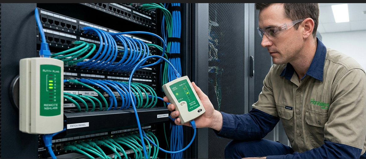
8. TESTING AFTER INSTALLATION (TRUNK 1 LINK)
All installations must be verified using structured testing methods.
Includes:
- OTDR testing
- Insertion loss testing
- Continuity checks
https://fibresales.com.au/fibre-optic-testing-performance-guide-australia/
REAL-WORLD ENGINEERING INSIGHT
In practice, fibre installation failures are rarely caused by the fibre itself. Instead, they come from small execution errors that accumulate across the network build.
Experienced technicians prioritise:
- Cleanliness over speed
- Controlled handling over force
- Testing after every critical step
This reduces rework and ensures long-term network stability.
For fibre optic installation products, splicing tools, and termination solutions, visit www.fibresales.com.au.