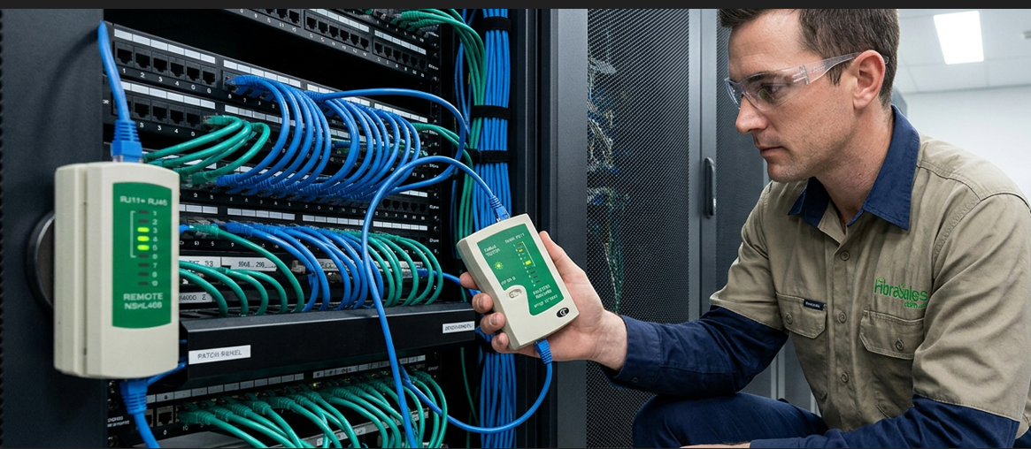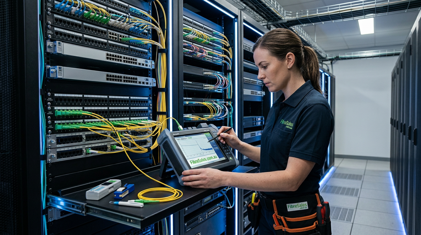
Fibre optic testing guide should do more than confirm that light passes through a cable. Professional fibre testing verifies whether an installed optical link performs within its required limits, identifies faults before they affect service and provides measurable evidence that the network has been installed correctly.
For Australian installers, contractors, network technicians and infrastructure managers, testing forms a critical part of installation, commissioning and ongoing maintenance. A fibre link may establish a connection while still suffering from excessive insertion loss, contamination, poor splices, excessive bending or reflective events that reduce its available performance margin.
Different tests answer different questions. An Optical Power Meter combined with a Light Source can measure end-to-end optical loss. Meanwhile, an OTDR can help technicians locate and analyse events along the fibre. Before testing, connector inspection and appropriate Fibre Cleaning Products help prevent contamination from affecting test results.
This guide explains the main fibre optic testing methods, the equipment used for each test and how to choose the correct testing approach. It also covers insertion loss, optical power, OTDR testing, connector inspection, link integrity, practical testing workflows and common mistakes that can produce misleading results.
What Is Fibre Optic Testing?
Fibre optic testing is the process of inspecting, measuring and verifying the condition and performance of an optical fibre link.
However, no single test answers every question. Depending on the installation, a technician may need to determine:
- whether the fibre has continuity;
- how much optical power reaches the receiving end;
- whether total link loss remains within the required limit;
- where a fault or high-loss event occurs;
- whether connectors contain contamination or physical damage;
- whether splices contribute excessive loss;
- whether reflective events could affect transmission;
- or whether the completed link meets the project specification.
Therefore, professional fibre testing usually combines several techniques rather than relying on one instrument. A Visual Fault Locator can help identify continuity problems or visible faults over shorter distances. A Light Source and Optical Power Meter can measure end-to-end optical loss. In contrast, an OTDR provides a distance-based view of the link and can help technicians identify connectors, splices, bends, breaks and other events.
For detailed power-meter procedures, see Optical Power Meter Guide: How to Test Fibre Optic Networks Accurately. The correct test depends on what you need to prove about the fibre link.
Why Fibre Optic Testing Matters
Optical networks depend on relatively small amounts of transmitted light passing through precisely manufactured fibre, connectors and splices. Consequently, seemingly minor installation problems can create measurable losses.
- contaminated connector end faces;
- damaged or poorly terminated connectors;
- excessive fibre bending;
- high-loss splices;
- incorrect reference procedures;
- unsuitable test leads;
- damaged fibre;
- mismatched components;
- and incorrect test equipment settings.
Testing identifies these issues before they become operational failures. If excessive loss is found, Insertion Loss Fibre Optics: Why You Should Care explains the measurement in more detail, while Troubleshooting High Loss Events in Fibre Optic Networks: The Complete Field Guide focuses on fault diagnosis.
Furthermore, this becomes particularly important in commercial networks, telecommunications infrastructure, data centres and high-speed backbone links. A network may initially appear to operate correctly yet have insufficient optical margin to remain dependable as equipment changes, connections age or network speeds increase.
Testing also creates a measurable baseline. Rather than assuming an installation is acceptable because active equipment establishes a connection, technicians can document the link’s optical performance and compare future results against the original commissioning data.
Which Fibre Optic Testing Method Do You Need?
The most effective way to select a testing method is to start with the question you need answered.
| What do you need to know? | Typical test method | Appropriate equipment |
| Is there basic continuity? | Visual continuity or fault check | Visual Fault Locator |
| How much optical power is present? | Optical power measurement | Optical Power Meter |
| What is the end-to-end optical loss? | Insertion loss testing | Light Source and Optical Power Meter |
| Where is a fault located? | OTDR testing | OTDR |
| Are connector end faces clean and undamaged? | Fibre inspection | Fibre Microscope |
| Are there splices, bends or reflective events? | Event analysis | OTDR |
| Does the completed link meet its required loss budget? | Acceptance testing | Light Source, Optical Power Meter and OTDR where required |
This distinction matters because the most advanced instrument is not automatically the correct instrument for every task. For example, an OTDR provides detailed information about events along an optical link, but it does not replace every end-to-end insertion loss test. Likewise, an optical power meter can measure received optical power, but it cannot identify the physical location of a high-loss event.
Therefore, equipment selection should follow the measurement requirement rather than the assumption that one tester can perform every role.
Fibre Optic Testing Guide – The Four Foundations of Reliable Fibre Testing
Reliable fibre testing follows a logical sequence: inspect, clean, measure and diagnose.
Inspect the Connector End Face
Before connecting test equipment, inspect connector end faces wherever the testing procedure permits. A Fibre Microscope allows technicians to identify contamination, scratches and other end-face defects that may affect optical performance.
For the inspection criteria and acceptance framework, see IEC 61300-3-35 Standard Explained and Fibre Optic Inspection Microscopes IEC 61300-3-35 Standard.
Inspection is important because connecting a contaminated connector can transfer debris onto a clean mating surface or directly onto expensive test equipment. Therefore, inspecting before connecting can prevent both inaccurate measurements and cross-contamination.
Clean Before Testing
If inspection identifies contamination, clean the connector using appropriate Fibre Cleaning Products and inspect it again before making the connection. For detailed cleaning procedures, see the Fibre Connector Cleaning Guide.
Cleaning should form part of the testing workflow rather than being treated as a separate maintenance task. Dirty connectors can increase insertion loss, produce reflective events and create inconsistent measurements. However, cleaning should not become a substitute for inspection. The preferred workflow is to inspect, clean when required and then inspect again before testing.
Measure the Fibre Link
Once the connectors are ready, use the test method that matches the required measurement. For end-to-end optical loss, a Light Source and Optical Power Meter provide the appropriate measurement method.
Alternatively, when the objective is to locate and characterise events along the fibre, an OTDR provides considerably more diagnostic information. In many professional installations, these methods complement rather than replace one another.
Diagnose Unexpected Results
If a measurement falls outside the expected range, the next step is to determine why.
- connector contamination;
- excessive insertion loss;
- a high-loss splice;
- a macro-bend;
- an unexpected reflective event;
- an incorrect reference measurement;
- damaged test cords;
- or physical fibre damage.
Combining inspection, loss testing and OTDR analysis can provide a much clearer picture than relying on one measurement alone. If an OTDR trace is part of the diagnosis, OTDR Event Table Explained | How to Read Fibre Test Results Like a Professional explains how to interpret event information without duplicating that specialist topic here.
Document the Final Test Results
Testing should finish with documentation. For commercial installations, recorded results provide evidence that the completed link met the required performance criteria at commissioning. In addition, those records establish a baseline for future maintenance and troubleshooting.
- fibre identification;
- test direction;
- test wavelength;
- measured optical loss;
- reference method;
- OTDR trace where required;
- connector and splice events;
- test equipment details;
- date of test;
- and technician or project information.
For guidance on interpreting completed records, see Fibre Test Report Explained | How to Read and Interpret Fibre Optic Test Results. If network performance changes later, technicians can compare new measurements against the commissioning results rather than beginning the investigation without historical data.
Engineering Decision: Test the Question, Not Just the Cable
The most important decision when choosing fibre test equipment is not simply:
Which tester should I buy?
Instead, ask:
What am I trying to prove about this fibre link?
To confirm basic continuity, a simple diagnostic method may be sufficient.
If you need to measure end-to-end optical loss, choose a Light Source and Optical Power Meter. If you need to locate and analyse faults, splices, bends or reflective events, an OTDR is the more appropriate diagnostic instrument.
For commissioning, acceptance testing and higher-value commercial infrastructure, technicians may require several testing methods because each instrument provides different information about the same optical link. Therefore, choosing the test according to the required measurement prevents both under-testing and unnecessary equipment selection while producing results that genuinely support the network’s technical requirements.
Core Fibre Optic Testing Methods
Once a fibre link has been inspected and prepared, the next step is to select the test method that answers the required technical question. In practice, technicians commonly use visual fault location, optical power measurement, insertion loss testing and OTDR analysis. Each method provides different information, so one test should not be treated as a substitute for all others.
The broad testing workflow belongs in this guide. However, specialist procedures remain with their dedicated owner articles. For example, detailed power-meter operation belongs in Optical Power Meter Guide: How to Test Fibre Optic Networks Accurately, while event interpretation belongs in OTDR Event Table Explained | How to Read Fibre Test Results Like a Professional.
Visual Fault Locator Testing
A visual fault locator (VFL) injects visible red light into a fibre so technicians can perform quick continuity checks and identify some localised faults. It is especially useful during installation, patching and basic troubleshooting where a fast visual indication is more valuable than a complete loss profile.
A VFL can help reveal incorrect routing, disconnected fibres, severe bends and some breaks where visible light escapes from the fibre. However, it does not measure insertion loss, optical power or the distance to every event with the precision of an OTDR.
For the complete use cases, limitations and safety considerations, see the Visual Fault Locator (VFL) Guide.
Optical Power Meter Testing
An Optical Power Meter measures the optical power arriving at a point in the fibre link. Depending on the test, technicians may use the reading to check transmitter output, received power or the performance of a link against an expected power level.
Power measurements are typically displayed in dBm. The tester must be configured for the correct wavelength because detector response and network specifications vary with wavelength. Reference levels, adapters and test cords also need to match the intended procedure.
For detailed instrument setup, reference procedures and measurement examples, use Optical Power Meter Guide: How to Test Fibre Optic Networks Accurately as the specialist owner article.
Insertion Loss Testing with a Light Source and Power Meter
When the goal is to determine the total end-to-end loss of a fibre link, technicians typically use a calibrated Light Source together with an Optical Power Meter. The source launches a known optical level into the fibre, while the meter measures the level received at the far end.
The difference between the reference level and the received level represents insertion loss. This method evaluates the link as an end-to-end system, including the fibre, connectors and splices that form part of the tested channel.
Because insertion loss is already owned by Insertion Loss Fibre Optics: Why You Should Care, this guide should use the concept for test selection rather than repeat the full technical explanation. Where technicians need to compare loss and reflection, Insertion Loss vs Return Loss Explained | Understanding the Difference in Fibre Optic Testing provides the dedicated comparison.
OTDR Testing and Fault Location
An OTDR sends pulses of light into the fibre and analyses the returned signal to build a distance-based trace of the link. This allows technicians to investigate where loss or reflection occurs rather than only measuring the total end-to-end result.
OTDR testing is particularly useful for locating breaks, high-loss splices, connectors, reflective events and bends. It can also support commissioning and troubleshooting where the physical location of an event matters.
However, OTDR configuration affects the quality of the trace. Wavelength, pulse width, averaging time, index settings, launch conditions and dynamic range all influence what the instrument can resolve. For the dedicated explanation of reach and measurement capability, see What is Dynamic Range in OTDR Testing (And Why It’s So Important).
Likewise, this broad guide should not reproduce a full OTDR event-by-event interpretation workflow. Technicians who need to interpret event tables should use OTDR Event Table Explained | How to Read Fibre Test Results Like a Professional.
Connector Inspection Before and During Testing
Test accuracy depends on the condition of the optical interfaces used during the measurement. A contaminated test lead or connector can introduce additional loss, create reflections and transfer contamination onto other mating surfaces.
A Fibre Microscope helps technicians inspect connector end faces before connection. Where contamination is present, appropriate Fibre Cleaning Products should be used before the connector is inspected again and connected to test equipment.
The detailed inspection criteria remain with IEC 61300-3-35 Standard Explained, while practical cleaning procedures remain with the Fibre Connector Cleaning Guide.
Choosing the Right Fibre Test Method
Use the measurement objective to choose the test method rather than selecting equipment by complexity alone.
| Testing objective | Best starting method | Primary equipment | What the result tells you |
| Quick continuity check | Visual fault location | Visual Fault Locator | Whether light continuity exists and some severe faults are visible |
| Measure received optical level | Optical power measurement | Optical Power Meter | Optical power present at the test point |
| Measure total link loss | Insertion loss test | Light Source + Optical Power Meter | End-to-end loss through the tested link |
| Locate and characterise events | OTDR analysis | OTDR | Distance and behaviour of events along the fibre |
| Check connector condition | Inspection | Fibre Microscope | Whether contamination or damage is visible on the end face |
Reference Levels and Test Consistency
A technically correct test can still produce misleading results if the reference procedure is inconsistent. Before loss testing, technicians should confirm the correct wavelength, clean and inspect reference connectors, use suitable reference-grade cords and follow the project or equipment procedure consistently.
Because reference setting is a specialised subject, this article should direct readers to Fibre Test Reference Values Explained: How to Set Accurate Reference Levels rather than duplicate the complete reference-level procedure.
Engineering Decision: Combine Tests When the Risk Justifies It
For a simple maintenance check, one test method may answer the immediate question. However, commissioning and higher-value commercial links often require more than one form of evidence.
For example, insertion loss testing can confirm whether the complete link remains within its loss budget, while OTDR analysis can show where individual events occur. Connector inspection helps protect the accuracy of both methods, and a VFL can provide a fast first check during fault isolation.
Therefore, the correct testing plan should be based on the consequence of failure, the project specification and the information required for acceptance. Where a result is outside the expected range, Troubleshooting High Loss Events in Fibre Optic Networks: The Complete Field Guide provides the next diagnostic step.
Frequently Asked Questions
What is the best way to test a fibre optic cable?
The best method depends on what you need to prove. For end-to-end optical loss, use a Light Source with an Optical Power Meter. If you need to locate a fault, splice, bend or reflective event, use an OTDR. Connector inspection should also form part of the workflow where applicable.
Can an OTDR replace an optical power meter and light source?
No. An OTDR and an insertion-loss test answer different questions. An OTDR provides a distance-based view of events along the fibre, while a light source and optical power meter measure end-to-end loss. The Fiber Optic Association also distinguishes these roles in its testing guidance.
What is insertion loss in fibre optic testing?
Insertion loss is the reduction in optical power through a fibre link, connector, splice or other component. This broad guide introduces the measurement, while Insertion Loss Fibre Optics: Why You Should Care owns the detailed explanation.
What is the difference between insertion loss and return loss?
Insertion loss measures optical power lost through a link or component, whereas return loss relates to light reflected back toward the source. For the dedicated comparison, see Insertion Loss vs Return Loss Explained | Understanding the Difference in Fibre Optic Testing.
Why should fibre connectors be inspected before testing?
Contamination and end-face damage can increase loss, create reflections and contaminate test equipment. Inspection with a Fibre Microscope helps identify problems before mating connectors. The inspection criteria are covered in IEC 61300-3-35 Standard Explained.
Should I clean a fibre connector every time before testing?
Inspect first. If contamination is present, use suitable Fibre Cleaning Products and inspect again before connection. This reduces the risk of spreading contamination or introducing avoidable test error.
What wavelengths should be used for fibre testing?
Use the wavelengths required by the fibre type, network design, project specification and applicable testing procedure. Recording the wavelength with the result is important because loss can vary with wavelength.
What is a fibre optic loss budget?
A loss budget estimates the total optical loss that a link can tolerate or is expected to contain. It helps installers compare measured performance with the design. See Fibre Optic Power Budget Calculator Guide: Understanding Link Loss and System Limits for the detailed calculation framework.
Why do OTDR tests use launch and receive cables?
Launch and receive cables help technicians evaluate the first and last connections outside the OTDR dead zones and provide more useful event information. Correct setup depends on the instrument, link and required test method.
How do I interpret an OTDR event table?
The event table summarises detected events such as connectors, splices, bends and reflective points. Rather than duplicating that specialist topic here, use OTDR Event Table Explained | How to Read Fibre Test Results Like a Professional for detailed interpretation.
What should be included in a fibre test report?
A useful report should identify the fibre, test direction, wavelength, test method, measured values, reference conditions and relevant traces or pass/fail criteria. Fibre Test Report Explained | How to Read and Interpret Fibre Optic Test Results covers report interpretation in detail.
Is fibre certification the same as qualification testing?
No. The terms describe different levels and purposes of verification. For the ownership boundary and practical distinction, see Fibre Certification vs Qualification Testing: What’s the Difference?.
Why fibresales for Fibre Optic Testing Equipment?
Reliable test results depend on choosing equipment that matches the measurement you need to perform. fibresales supplies professional OTDRs, Optical Power Meters, Light Sources, Fibre Microscopes and Fibre Cleaning Products for installation, commissioning, maintenance and troubleshooting.
The practical advantage is selection by task rather than by instrument name alone. If the job requires end-to-end loss measurement, the appropriate light source and power meter matter more than buying an OTDR simply because it is the more advanced instrument. Conversely, fault location and event analysis require the distance-based information an OTDR can provide.
Fibre Optic Testing Guide Conclusion
A reliable fibre optic testing guide must connect the test method to the question being asked. Continuity, optical power, insertion loss, connector condition and fault location are related, but they are not the same measurement.
For professional commissioning, technicians should inspect and clean connectors, set references correctly, test at the required wavelength, compare results with the expected loss budget and document the final measurements. Where results fall outside expectations, targeted OTDR analysis and specialist troubleshooting can then identify the likely cause.
Choosing the correct combination of OTDR, Optical Power Meter, Light Source, inspection equipment and cleaning tools helps produce measurements that support confident commissioning and faster fault diagnosis.
Shop fibresales
For fibre installation and testing projects, explore the fibresales ranges of OTDRs, Optical Power Meters, Light Sources, Fibre Microscopes and Fibre Cleaning Products to match the test method to the application.
For more fibre optic solutions, technical resources, and installation products, visit www.fibresales.com.au.
Continue Learning
- Optical Power Meter Guide: How to Test Fibre Optic Networks Accurately – Explains optical power and end-to-end testing procedures in greater depth.
- Fibre Test Reference Values Explained: How to Set Accurate Reference Levels – Covers how reference levels affect insertion-loss measurements and repeatability.
- Fibre Optic Power Budget Calculator Guide: Understanding Link Loss and System Limits – Shows how to estimate expected link loss and compare measured results with design limits.
- OTDR Event Table Explained | How to Read Fibre Test Results Like a Professional – Explains how OTDR event tables identify and classify events along a fibre link.
- Troubleshooting High Loss Events in Fibre Optic Networks: The Complete Field Guide – Provides a field-focused process for diagnosing unexpectedly high optical loss.
- IEC 61300-3-35 Standard Explained – Explains the connector end-face inspection criteria used to assess cleanliness and defects.
- Insertion Loss vs Return Loss Explained | Understanding the Difference in Fibre Optic Testing – Clarifies the difference between transmitted loss and reflected optical power.
- Fibre Test Report Explained | How to Read and Interpret Fibre Optic Test Results – Explains how to interpret documented test results after measurements are complete.
References
- The Fiber Optic Association – Optical Time Domain Reflectometer (OTDR) – Explains OTDR applications, limitations, event analysis and the role of launch/receive cables.
- The Fiber Optic Association – Understanding the Math of Insertion Loss Testing – Describes light-source and power-meter reference methods used for insertion-loss testing.
- The Fiber Optic Association – Fibre Optic Reference Cables – Provides guidance on reference cable use and test conditions for loss measurements.
- IEC 61300-3-35:2022 – Fibre Optic Connector End-Face Inspection – Defines procedures and quantitative criteria for inspection of fibre-optic connector end faces.
- TIA – ANSI/TIA-568.3-D Optical Fiber Cabling and Component Standard – Describes premises optical fibre cabling requirements and includes connector testing and field-testing guidance.