IEC 61300-3-35 Standard for Fibre Inspection | Complete Guide
IEC 61300-3-35 Fibre Inspection Standard Explained
When it comes to reliable fibre optic networks, connector cleanliness is one of the most important factors affecting performance. Even microscopic contamination can increase insertion loss, create unwanted reflections and lead to intermittent network failures.
To ensure consistent inspection practices across the industry, the IEC 61300-3-35 inspection standard defines how fibre optic connector end faces should be inspected and establishes objective pass/fail criteria based on the size and location of defects.
Whether you’re commissioning a new fibre installation, maintaining an enterprise network or troubleshooting unexplained attenuation, understanding the IEC 61300-3-35 inspection standard helps ensure every connector meets an internationally recognised level of quality.
If you’re new to fibre optic testing, our Fibre Optic Testing Performance Guide explains the complete testing process before exploring inspection standards in greater detail.
Professional inspections require the correct equipment. FibreSales supplies professional Inspection Microscopes and Cleaning Products to help technicians inspect, clean and certify fibre optic connectors in accordance with industry best practice.
What Is the IEC 61300-3-35 Inspection Standard?
The IEC 61300-3-35 inspection standard is an international standard that specifies the inspection and cleaning requirements for fibre optic connector end faces.
Rather than relying on subjective visual assessment, the standard defines measurable acceptance criteria based on the location and size of defects such as dust, scratches, pits and contamination.
The objective is simple:
Every connector should be inspected before it is connected to another fibre.
This supports the industry’s widely accepted principle:
Inspect. Clean. Inspect Again. Connect.
Following this process significantly reduces connector-related faults and improves long-term network reliability.
Why the IEC 61300-3-35 Inspection Standard Is Important
The IEC 61300-3-35 inspection standard helps ensure consistent inspection practices regardless of the technician or project.
Without a recognised inspection standard:
- Connector cleanliness becomes subjective.
- Test results become inconsistent.
- Insertion loss may increase.
- Return loss may deteriorate.
- Connectors can permanently damage one another.
A single contaminated connector can transfer debris to multiple patch leads, significantly increasing maintenance costs across the network.
If connector contamination is contributing to high attenuation, our Insertion Loss vs Return Loss Explained article explains how contamination affects both measurements.
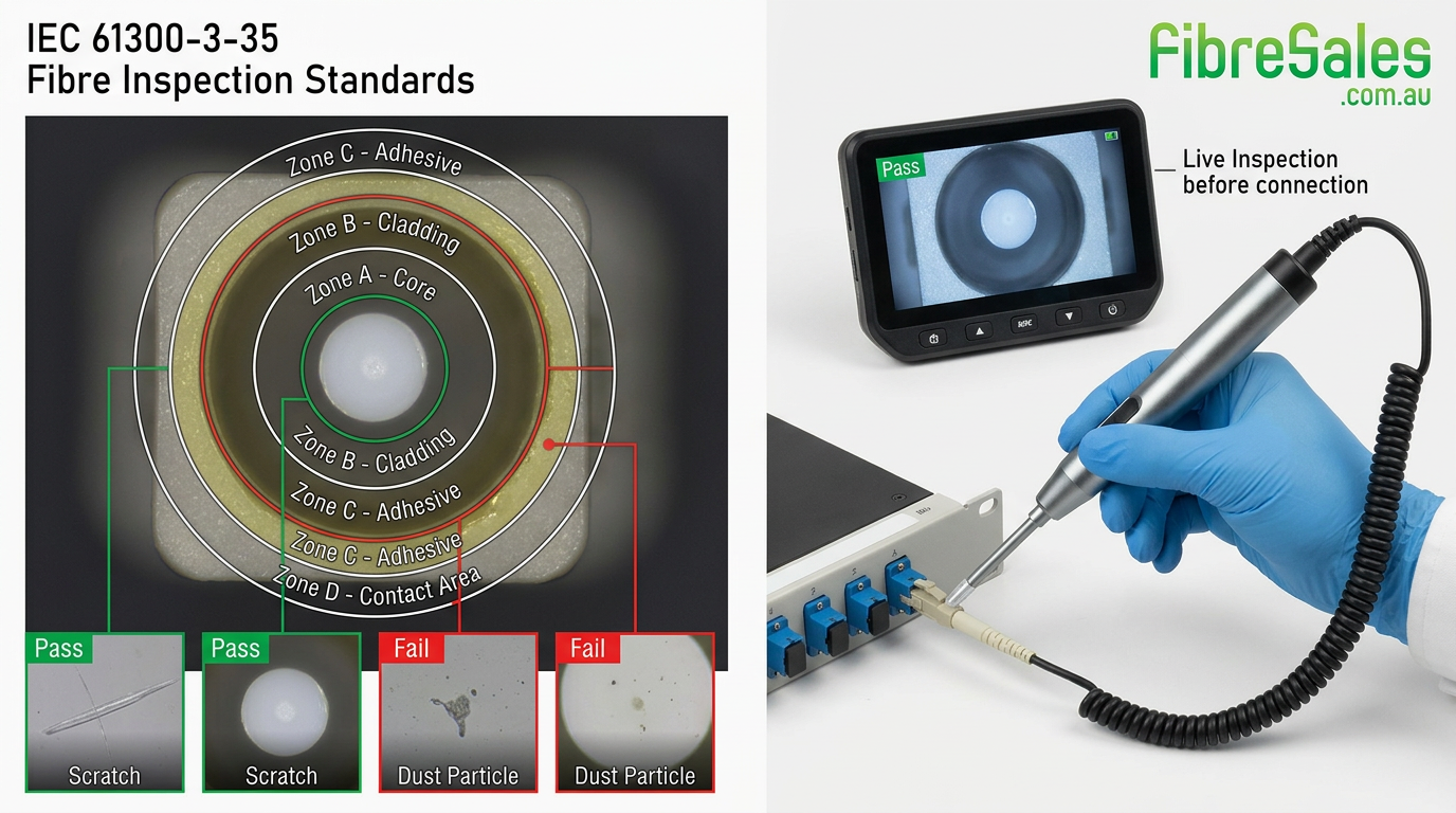
IEC 61300-3-35 Inspection Standard Inspection Zones
One of the key features of the IEC 61300-3-35 inspection standard is dividing the connector ferrule into inspection zones.
| Zone | Description | Importance |
|---|---|---|
| Zone A | Fibre Core | Critical – No contamination permitted |
| Zone B | Cladding | Very High |
| Zone C | Adhesive/Bond Area | Moderate |
| Zone D | Ferrule Contact Area | Lower |
Defects located within the fibre core have the greatest effect on optical performance because this is where the optical signal is transmitted.
Engineering Tip
Small particles on the ferrule edge may be acceptable, but contamination within the fibre core almost always requires cleaning before the connector is placed into service.
Cleaning is a fundamental step in maintaining fibre optic systems, but is it enough to guarantee optimal network performance? Unfortunately, no. While cleaning removes contaminants, inspection is equally critical to ensure fibre optic connectors meet industry standards and function as intended.
What Defects Does the IEC 61300-3-35 Inspection Standard Look For?
The IEC 61300-3-35 inspection standard evaluates several types of connector defects.
These include:
- Dust
- Dirt
- Oil residue
- Fingerprints
- Scratches
- Pits
- Chips
- Epoxy residue
The size and location of each defect determines whether the connector passes or fails inspection.
Professional Inspection Microscopes automatically analyse these defects against IEC 61300-3-35 criteria, reducing operator subjectivity and improving consistency.
How to Perform an IEC 61300-3-35 Inspection
Following the IEC 61300-3-35 inspection standard is straightforward when the correct process is used.
- Inspect the connector.
- Compare the image with IEC 61300-3-35 criteria.
- If contamination is present, clean the connector using professional Cleaning Products
- Reinspect the connector.
- Repeat if necessary.
- Connect only after the connector passes inspection.
This process prevents contamination from being transferred to otherwise clean connectors.
Common Causes of Failed Inspections
The most common reasons connectors fail the IEC 61300-3-35 inspection standard include:
- Dust from patch panels
- Fingerprints
- Protective caps removed too early
- Poor storage practices
- Dirty cleaning tools
- Damaged ferrules
- Oil contamination
Many failed inspections can be corrected through proper cleaning without replacing the connector.
Consequences of Fibre Contamination
Contaminated fibre can lead to a range of serious issues, including:
- High Link Loss & Connector Loss – Reducing overall signal strength and efficiency.
- Failed Optical Return Loss (ORL) – Leading to poor signal integrity.
- Relative Intensity Noise (RIN) – Caused by reflections that interfere with signal quality.
- Wasted Troubleshooting Time – Hours lost diagnosing avoidable problems.
- Network Outages – Unplanned downtime due to preventable failures.
- Increased Failure Rates – Costly repairs and replacements.
IEC 61300-3-35 Inspection Standard and OTDR Testing
Connector contamination often appears during OTDR testing as increased insertion loss or reflective events.
If your OTDR identifies a high-loss connector, don’t replace it immediately.
Instead:
- Inspect the connector.
- Clean it.
- Reinspect it.
- Repeat the OTDR test.
Our OTDR Event Table Explained guide explains how contaminated connectors appear during OTDR analysis.
Common Mistakes When Following the Inspection Standard
Even experienced technicians can make avoidable mistakes.
Common mistakes include:
- Connecting fibres without inspection.
- Inspecting only one side of the connection.
- Reusing dirty cleaning sticks.
- Assuming new patch leads are clean.
- Ignoring microscope calibration.
- Failing to reinspect after cleaning.
Common Mistake
Never assume a brand-new patch lead is free from contamination. Every connector should be inspected before its first use, regardless of its packaging.
If contamination repeatedly causes network failures, our Fibre Connector Troubleshooting Guide provides a structured fault-finding process.
Real-World Field Scenario
A contractor commissioning a data centre repeatedly failed insertion loss testing on several links. OTDR results suggested excessive loss at multiple connector locations.
Instead of replacing patch leads, the technician inspected every connector using an Inspection Microscope. Several connectors failed the IEC 61300-3-35 inspection standard due to contamination within the fibre core.
After cleaning the connectors with professional Cleaning Products and reinspecting them, all connectors passed inspection. The links subsequently passed insertion loss testing, avoiding unnecessary replacement costs and project delays.
Best Practices for the IEC 61300-3-35 Inspection Standard
To achieve consistent inspection results:
- Inspect every connector before mating.
- Clean connectors whenever contamination is detected.
- Reinspect after cleaning.
- Use automated inspection where possible.
- Protect connectors with dust caps during storage.
- Replace damaged connectors rather than attempting repair.
- Record inspection images where required for quality assurance.
Consistently following these practices reduces network faults and extends the life of fibre optic connectors.
Engineering Decision Insight
The inspection standard has transformed fibre optic connector inspection from a subjective visual process into a measurable quality control procedure. By applying objective pass/fail criteria and adopting the “Inspect, Clean, Inspect Again, Connect” workflow, technicians can dramatically reduce connector-related faults and improve network reliability.
When combined with proper insertion loss testing, OTDR analysis and comprehensive documentation, compliance with IEC 61300-3-35 provides confidence that every fibre connection has been inspected to an internationally recognised standard.
The Importance of Inspection
Some contaminants are stubborn and require multiple cleanings or wet/dry cleaning methods. Visual inspection ensures that a connector is properly cleaned and free from defects before being put into operation.
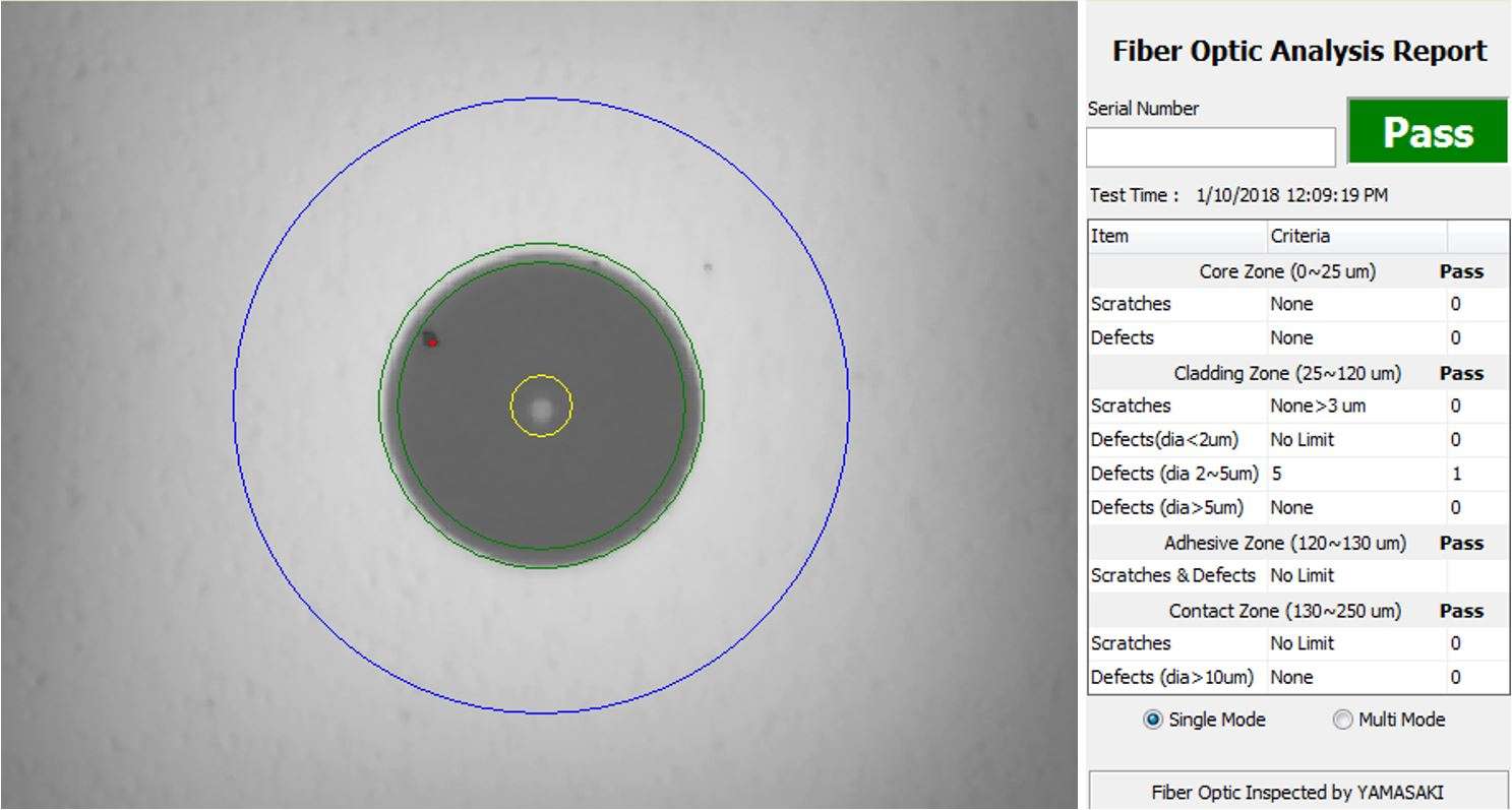
To standardize inspections and improve repeatability, the International Electrotechnical Commission (IEC) established IEC 61300-3-35, a standard that defines cleanliness grading criteria. It classifies:
- Scratches – Permanent linear surface features.
- Defects – Including pits, chips, embedded particles, loose debris, and cracks.
These standards segment the fibre into distinct measurement zones:
- Core
- Cladding
- Adhesive Layer
- Contact Zone
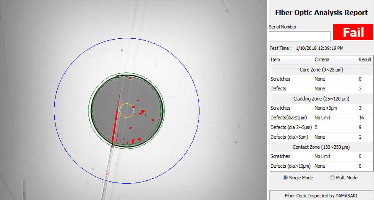
Certification criteria vary based on:
- Connector type
- Fibre size
- Types and severity of defects
Methods of Fibre End Face Inspection
There are two primary ways to inspect fibre optic connectors:
1. Objective Method: Handheld Microscopes
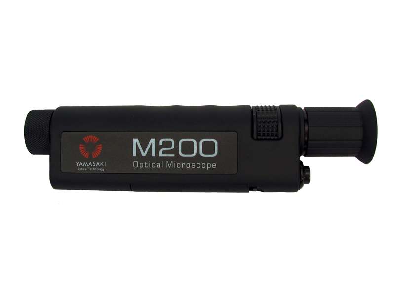
Example: Yamasaki M200 Handheld Microscope
- Cost-effective for basic inspection.
- Requires manual assessment using IEC 61300-3-35 as a guideline.
- Accuracy depends on technician expertise.
- Potential Risk: Direct exposure to laser light if safety precautions aren’t followed.
- Safety Measure: Devices like the Yamasaki M200 and M400 include an “Optima GRB3” safety filter to protect the eyes.
Note; that the safety filter in the Yamasaki M200 and M400 is called “Optima GRB3” and is a high transmission heat absorbing filter.
2. Automated Certification: Algorithm-Based Inspection
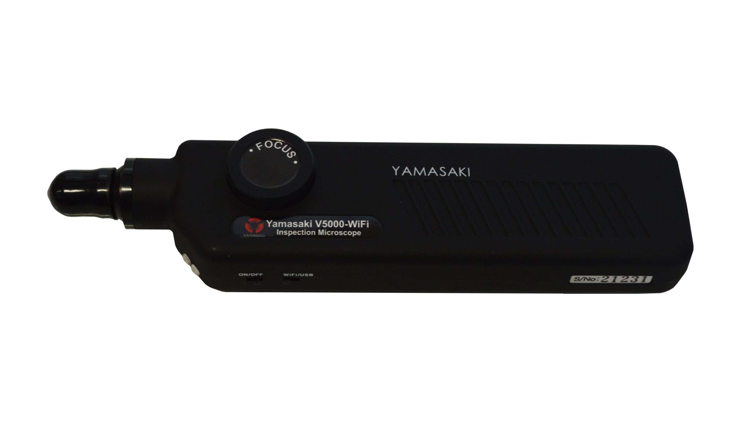
Example: Yamasaki V5000 WiFi
- Uses software-driven algorithms to inspect, grade, and certify connectors automatically.
- Eliminates human error and inconsistency.
- Provides Pass/Fail analysis.
- Safe for eyes—no direct exposure to laser light.
- Can be used on PCs or mobile devices, offering real-time results.
- Enables certifiable inspection reports for documentation and compliance.
Conclusion
Following the IEC inspection standard is one of the simplest and most effective ways to improve fibre optic network reliability. By inspecting every connector, cleaning contamination correctly and verifying compliance before connection, technicians can minimise insertion loss, reduce return loss issues and prevent unnecessary troubleshooting.
For professional For professional Inspection Microscopes, OTDRs , Power Meters, Light Sources, and Cleaning Products , visit www.fibresales.com.au to explore Australia’s trusted range of fibre optic testing equipment, connector inspection tools and technical resources.
- Continue Learning
- Optical Power Meter Guide
- Optical Return Loss Explained
- OTDR Event Table Explained
- Fibre Optic Power Budget Guide
- Insertion Loss vs Return Loss