Troubleshooting High Loss Events in Fibre Optic Networks: The Complete Field Guide
Unexpected high loss events are among the most common reasons for fibre optic network failures. Whether you’re commissioning a new installation, investigating intermittent communication issues or certifying a completed link, identifying the source of excessive optical loss quickly can save hours of troubleshooting and unnecessary cable replacement.
High loss events can occur anywhere within a fibre link—from contaminated connectors and poor fusion splices to damaged patch leads or excessive bending. While modern test equipment makes locating these faults easier than ever, successful troubleshooting still relies on understanding what the results actually mean.
This guide explains how to identify, locate and resolve high loss events using industry best practices, helping Australian fibre technicians diagnose problems efficiently while avoiding common mistakes.
Troubleshooting High Loss Events – What Is a High Loss Event?
A high loss event is any point within a fibre optic link where optical power is reduced more than expected.
Unlike normal fibre attenuation, which occurs gradually over distance, a high loss event is typically localised to a specific component or section of cable.
Examples include:
- Contaminated connectors
- Poor fusion splices
- Damaged patch leads
- Excessive macro-bending
- Crushed or damaged cable
- Defective adaptors
- Incorrectly terminated connectors
Every high loss event reduces the available optical power reaching the receiver and consumes part of the network’s available link budget.
For an overview of optical loss calculations, read our Fibre Optic Power Budget Calculator Guide.
Troubleshooting High Loss Events – Why High Loss Matters
Even relatively small increases in insertion loss can significantly reduce network performance.
Excessive loss may result in:
- Intermittent network outages
- Reduced transmission distance
- Failed certification tests
- High Bit Error Rates (BER)
- Poor system reliability
- Reduced operating margin
- Future network failures as components continue to degrade
Modern 10G, 25G, 40G and 100G networks often have very little spare optical budget, making every connector and splice important.
Troubleshooting High Loss Events – The Most Common Causes
Dirty Connectors
The most common cause of excessive loss is connector contamination.
Dust, oils and microscopic debris prevent proper physical contact between fibre end faces, increasing both insertion loss and optical reflections.
Before performing any measurements:
- Inspect every connector
- Clean using approved fibre cleaning tools
- Re-inspect before connecting
Related Products
Fibre inspection microscopes and fibre cleaning kits should be considered essential equipment for every technician.
Poor Fusion Splices
A correctly completed fusion splice should introduce minimal loss.
Common splice problems include:
- Core misalignment
- Contamination
- Poor cleave angle
- Incorrect arc calibration
- Damaged fibre coating
OTDR testing usually identifies poor splices as localised loss events.
Damaged Patch Leads
Patch leads often experience:
- Excessive bending
- Connector wear
- Contamination
- Physical damage
Because they are frequently handled, they are one of the first components that should be checked during troubleshooting.
Using certified low-loss patch leads significantly improves network reliability.
Macro-Bending
Macro-bending occurs when fibre is bent tighter than its minimum bend radius.
Typical causes include:
- Overfilled cable trays
- Tight patch panel management
- Incorrect storage
- Sharp cabinet corners
Macro-bending becomes increasingly significant at longer wavelengths such as 1550 nm.
Micro-Bending
Micro-bending is caused by tiny stresses applied to the fibre.
Examples include:
- Overtight cable ties
- Compression inside closures
- Poor cable management
- Manufacturing defects
Unlike macro-bending, micro-bending is often difficult to identify visually.
Damaged Adaptors
A worn or damaged adaptor can introduce:
- Misalignment
- Excessive insertion loss
- Increased return loss
- Intermittent faults
Replacing a suspect adaptor is often faster than prolonged troubleshooting.
Equipment Used to Troubleshoot High Loss Events
Different faults require different testing methods.
| Equipment | Primary Purpose | Best Used For |
|---|---|---|
| Optical Power Meter | Total insertion loss | Certification and acceptance testing |
| Optical Light Source | Reference testing | End-to-end loss measurement |
| OTDR | Locate individual events | Fault location and analysis |
| Visual Fault Locator (VFL) | Continuity and visible faults | Short-distance fault finding |
| Inspection Microscope | Connector inspection | Detecting contamination and damage |
Using multiple testing methods provides the most accurate diagnosis.
Recommended Troubleshooting Workflow
Following a structured process helps eliminate simple faults before progressing to more advanced testing.
Step 1 – Confirm the Fault
Verify the reported issue and identify whether it affects:
- One fibre
- Multiple fibres
- An entire cable
- A specific service
Step 2 – Inspect Every Connector
Never assume connectors are clean.
Inspect each connector using a fibre inspection microscope before cleaning.
Even connectors fitted with dust caps should be inspected.
Step 3 – Clean and Re-Test
After inspection:
- Clean connectors
- Reconnect
- Repeat insertion loss testing
Many apparent network faults disappear after proper cleaning.
Step 4 – Measure Insertion Loss
Using an optical light source and power meter:
- Compare measured loss with design specifications.
- Identify whether the total link exceeds the allowable budget.
If you’re unsure how to perform this test, see our Optical Power Meter Guide
Step 5 – Perform OTDR Testing
If insertion loss remains excessive:
Use an OTDR to identify:
- High-loss connectors
- Poor fusion splices
- Cable damage
- Reflection events
- Fibre breaks
The OTDR event table will normally pinpoint the location of abnormal loss.
Step 6 – Isolate the Fault
Replace or repair components one at a time.
Common isolation methods include:
- Swapping patch leads
- Replacing adaptors
- Re-splicing suspect joints
- Bypassing equipment
- Re-testing after every change
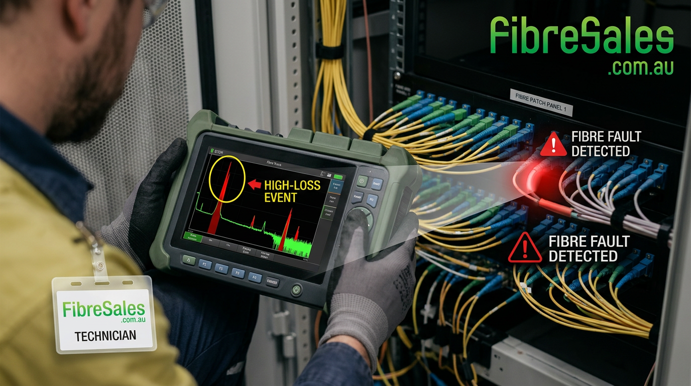
Understanding OTDR High Loss Events
A typical OTDR trace may reveal:
| Event Type | Possible Cause |
|---|---|
| Small gradual increase | Normal attenuation |
| Sharp loss with no reflection | Fusion splice |
| Sharp loss with reflection | Connector fault |
| Large reflection spike | Dirty connector or open fibre |
| Sudden end of trace | Fibre break |
Understanding event signatures significantly reduces troubleshooting time.
For more information, read our OTDR Event Table Explained guide.
Engineering Tips
Always Test Both Directions
Bi-directional testing provides a more accurate representation of splice performance.
Replace the Patch Lead First
A faulty patch lead is considerably more common than damaged installed cable.
Replacing it can eliminate many faults in minutes.
Clean Before Every Test
Inspection without cleaning—or cleaning without inspection—should never be considered best practice.
Verify the Reference
Incorrect reference cables or poor referencing procedures frequently produce misleading loss results.
Record Every Result
Maintaining historical test records makes future fault diagnosis significantly easier.
Common Mistakes
Replacing Fibre Before Testing
Cable replacement should be the last option, not the first.
Ignoring Dirty Connectors
Connector contamination remains the leading cause of network faults.
Assuming OTDR Replaces Loss Testing
OTDRs locate faults.
Power meters certify loss.
Both tests are required.
Using Poor Quality Reference Leads
Reference leads directly affect measurement accuracy.
Certified low-loss reference cables should always be used.
Real-World Example
A customer reported intermittent communication failures across a newly installed singlemode backbone.
Initial suspicion focused on a damaged underground cable.
Testing revealed:
- Total insertion loss exceeded specifications by 1.8 dB.
- OTDR identified a significant event inside the communications rack.
- Inspection found contamination on an LC connector introduced during installation.
After cleaning and retesting:
- Loss returned within specification.
- No cable replacement was required.
- The network passed final certification.
The issue was resolved in less than 30 minutes.
Troubleshooting High Loss Events – Recommended Products
Successful fault diagnosis depends on using the right tools. FibreSales stocks a comprehensive range of professional fibre optic testing equipment, including:
- OTDRs for locating high-loss events and fibre breaks.
- Optical Power Meters and Light Sources for insertion loss testing and link certification.
- Visual Fault Locators (VFLs) for rapid continuity checks and locating visible faults.
- Fibre Inspection Microscopes for identifying contamination and end-face damage before testing.
- One-Click Fibre Cleaners and Cleaning Kits to remove dust and debris from connectors.
- Reference Test Leads for accurate OLTS testing and compliant certification.
- Low-Loss Fibre Patch Leads to replace damaged or suspect assemblies during fault isolation.
- Fibre Adaptors and Accessories to ensure reliable test setups and minimise measurement errors.
Using quality test equipment and accessories helps eliminate false readings, reduces troubleshooting time and improves the reliability of certification results.
For professional OTDRs , Power Meters, Light Sources, Cleaning Products and Inspection Microscopes, visit www.fibresales.com.au to explore Australia’s growing resource centre for fibre optic products, technical guides and professional testing solutions.
Frequently Asked Questions
What causes high loss in fibre optic cables?
The most common causes are contaminated connectors, poor fusion splices, damaged patch leads, excessive bending and connector misalignment.
Can a dirty connector really cause a test failure?
Yes. Even microscopic contamination can increase insertion loss enough to cause certification failures, particularly on high-speed networks.
Should I use an OTDR or a power meter first?
Start by measuring the total insertion loss using an optical power meter. If excessive loss is detected, use an OTDR to locate the specific high-loss event.
Can high loss events become worse over time?
Yes. Contamination, mechanical stress and deteriorating connectors can progressively increase optical loss if not corrected.
Continue Building Your Fibre Optic Testing Knowledge
If you found this guide useful, continue exploring our Fibre Optic Testing series:
- Optical Power Meter Guide
- Optical Return Loss Explained
- OTDR Event Table Explained
- Fibre Optic Power Budget Guide
- Insertion Loss vs Return Loss
- Fibre Test Report Explained
- Fibre Optic Testing & Performance Guide (AU)
- Visual Fault Locator (VFL) Guide
Together, these resources provide a practical knowledge base for testing, certifying and troubleshooting modern fibre optic networks.