Fibre Test Reference Values Explained: How to Set Accurate Reference Levels
Accurate fibre optic testing begins long before the first measurement is taken. One of the most important steps is establishing the correct fibre test reference values, which provide the baseline against which all insertion loss measurements are compared.
If the reference is incorrect, every subsequent test result will also be incorrect. Even a perfectly installed fibre optic link can appear to fail certification if the reference values have not been established correctly.
Whether you’re commissioning a new network, troubleshooting excessive attenuation or certifying a completed installation, understanding fibre test reference values is fundamental to producing reliable and repeatable test results.
If you’re new to fibre testing, begin with our Fibre Optic Testing Performance Guide, which explains the complete testing process before examining reference methods in detail.
Professional testing begins with reliable equipment. FibreSales supplies a comprehensive range of OTDRs, Power Meters, Light Sources , Cleaning Products and Inspection Microscopes, to support professional fibre installation and certification.
What Are Fibre Test Reference Values?
Fibre test reference values are the baseline optical power measurements established before insertion loss testing begins.
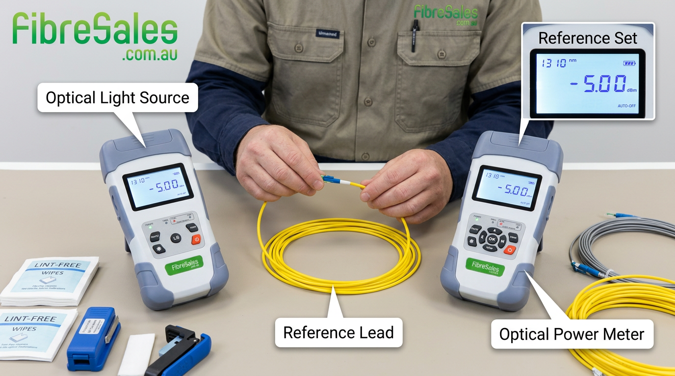
The optical power meter records the amount of optical power received directly from a calibrated light source. This value becomes the reference against which the installed fibre link is measured.
Any reduction in received power after the fibre under test is connected is recorded as insertion loss.
Without accurate reference values, insertion loss measurements become meaningless because the baseline itself is incorrect.
For a detailed explanation of insertion loss calculations, see our Optical Power Meter Guide and Insertion Loss vs Return Loss Explained .
Why Test Reference Values Are Important
Correct fibre test reference values ensure every measurement accurately reflects the performance of the installed fibre rather than variations in the test equipment.
Incorrect reference values may result in:
- False pass results.
- False failure results.
- Unnecessary troubleshooting.
- Incorrect acceptance reports.
- Additional labour costs.
- Project delays.
Engineering Decision
Always establish new reference values whenever reference leads are changed, connectors are cleaned or test equipment is reconfigured.
Fibre Test Reference Values and the One-Cord Reference Method
The one-cord reference method is widely regarded as the preferred method for insertion loss testing because it introduces the fewest connector interfaces into the reference.
The process is straightforward:
- Connect the calibrated light source directly to the power meter using a high-quality reference lead.
- Clean and inspect both connectors before making the connection.
- Set the reference value.
- Disconnect only the end required to insert the fibre under test.
Because fewer connector interfaces are included, the one-cord method generally provides the most accurate baseline.
Fibre Test Reference Values and the Two-Cord Reference Method
The two-cord reference method introduces an additional reference lead into the setup.
This method was historically common and appears in older practices, but it is not the preferred certification method in Australia today. The current fibre testing standards have moved toward more accurate reference methods, including the one-cord reference method and, where applicable, enhanced methods.
Some manufacturers and legacy documentation still refer to 2-cord or method B testing, so the contract specification matters. A mining, defence, government or data-centre project may specify its own testing procedure.
Fibre Test Reference Values and the Three-Cord Reference Method
The three-cord reference method is generally reserved for situations where testing requirements or connector configurations make it unavoidable.
For current Australian structured cabling certification, the traditional Three-Test-Cord Reference Method (3 TCRM) is not the normal accepted method. It was removed from the AS/NZS 14763.3:2017 approach. However, an Enhanced Three-Test-Cord Reference Method was introduced for specific situations, particularly where there are connector interface mismatches.
Although acceptable under certain testing procedures, every additional connector interface increases the potential for measurement uncertainty.
Whenever possible, minimise unnecessary reference connections to improve measurement accuracy.
Inspect each connector using an Inspection Microscope and clean them with professional Cleaning Products before establishing the reference.
Preferred:
- 1-cord reference method (where possible)
- Calibrated OLTS/light source + power meter testing
- OTDR as supplementary diagnostic testing
Use enhanced 3-cord only when:
- Connector types cannot be matched
- The project specification requires it
- You are documenting the reason for using it
Enhanced 3-cord method
The enhanced method is different. It is intended mainly for cases such as:
- The tester has one connector type, but the installed fibre has another.
- You cannot directly mate the test equipment to the installed link.
- You need to account for connector interface losses correctly.
Example:
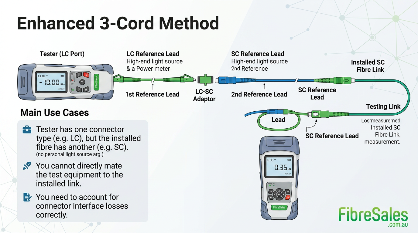
The enhanced method allows the measurement uncertainty caused by these mismatches to be controlled.
Common Mistakes When Setting Reference Values
Many testing errors occur before the fibre under test is even connected.
Common mistakes include:
- Using dirty reference leads.
- Mixing multimode and singlemode reference cords.
- Selecting the wrong wavelength.
- Changing reference leads without resetting the reference.
- Using damaged patch leads.
- Forgetting to inspect connectors.
- Referencing through unnecessary adaptors.
Common Mistake
Reference leads are precision measurement tools. They should be inspected, cleaned and protected to a higher standard than ordinary patch leads.
Fibre Test Reference Values and Connector Cleanliness
Connector contamination remains one of the leading causes of incorrect fibre test reference values.
Even microscopic dust particles can reduce the measured reference power and produce misleading insertion loss results.
The recommended workflow is:
- Inspect.
- Clean.
- Inspect again.
- Set the reference.
- Perform testing.
This procedure aligns with the guidance discussed in our IEC 61300-3-35 Fibre Inspection Standard Explained article.
Fibre Test Reference Values and OTDR Testing
Although an OTDR does not require insertion loss reference values in the same way as a power meter, both instruments complement one another.
An OTDR identifies the location of high-loss events, while insertion loss testing confirms the overall performance of the complete fibre link.
If insertion loss exceeds expectations after establishing correct reference values, our OTDR Event Table Explained guide helps identify the location of the problem.
Real-World Field Scenario
A contractor was commissioning a 48-core singlemode backbone between two communications rooms. Initial insertion loss testing indicated that several fibres exceeded the project’s allowable loss budget.
Before scheduling costly re-splicing, the lead technician reviewed the testing procedure and discovered that one reference lead had been replaced after the reference values were established.
The technician inspected the replacement lead using an Inspection Microscope, cleaned the connectors, established new fibre test reference values and repeated the insertion loss tests.
All fibres subsequently met the project specification, preventing unnecessary remedial work and saving several hours of labour.
Best Practices
To establish reliable fibre test reference values:
- Use calibrated test equipment.
- Use high-quality reference leads.
- Inspect every connector before testing.
- Clean all connectors before establishing the reference.
- Match the wavelength to the network.
- Re-establish the reference whenever the test configuration changes.
- Record the reference method used in the test report.
Consistent reference procedures improve measurement repeatability and reduce unnecessary troubleshooting.
Engineering Decision Insight
Accurate fibre test reference values form the foundation of reliable insertion loss testing. Regardless of the quality of the test equipment, incorrect reference procedures can invalidate every measurement taken afterwards.
By following recognised reference methods, maintaining clean reference leads and verifying connector condition before testing, technicians can achieve repeatable, standards-compliant results that accurately reflect network performance.
References
For additional technical guidance, consult:
- The Fibre Optic Association (FOA) – Fibre optic testing best practices.
- IEC 61280 series – Fibre optic communication subsystem test procedures.
- TIA-568 – Optical fibre cabling standards.
Conclusion
Establishing accurate fibre test reference values is one of the most critical steps in fibre optic testing. A correctly referenced optical power meter provides the baseline needed for meaningful insertion loss measurements, ensuring that certification results reflect the true performance of the installed network. The one-cord reference method is preferred because it gives the most accurate measurement of the actual fibre link loss by removing uncertainty from the reference setup. The two-cord reference method was historically common and appears in older practices, but it is not the preferred certification method in Australia today. AS/NZS 14763.3 also does not recommend the traditional three-test-cord reference method for general certification testing. Where connector interface mismatches prevent use of the one-cord reference method, the enhanced three-test-cord reference method may be used.
For professional Inspection Microscopes, OTDRs , Power Meters, Light Sources, and Cleaning Products , visit www.fibresales.com.au to explore Australia’s trusted range of fibre optic testing equipment, connector inspection tools and technical resources.