Fibre Optic Attenuation Troubleshooting Guide: Causes, Diagnosis, and Signal Loss Control
Fibre Optic Attenuation Troubleshooting Guide – Introduction
Attenuation is one of the most important performance metrics in any optical network. When signal loss exceeds acceptable thresholds, network stability begins to degrade even if the fibre link remains physically intact.
In real deployments, attenuation issues are rarely caused by a single fault. Instead, they result from accumulated losses across connectors, splices, bends, and transceiver limitations.
Effective troubleshooting requires understanding where loss is introduced and how each element in the optical path contributes to total system performance.
Fibre Optic Attenuation Troubleshooting Guide: What Attenuation Actually Means
Attenuation refers to the reduction in optical signal strength as it travels through a fibre link.
In practical terms, attenuation determines whether a signal arrives at the receiving device with enough power to maintain reliable communication.
Decision logic:
If a link is unstable over distance but works over short runs, attenuation rather than hardware failure should be assumed first.
Fibre Optic Attenuation Troubleshooting Guide: Common Causes of Signal Loss
Most attenuation issues come from predictable physical or installation-related factors.
Primary causes:
- dirty or contaminated connectors
- excessive splice loss
- tight bend radius violations
- poor-quality patch leads
- ageing or damaged fibre infrastructure
Decision logic:
Technicians prioritise inspection of physical interfaces before testing active equipment because optical loss is most commonly introduced at connection points.
Fibre Optic Attenuation Troubleshooting Guide: Connector Loss and Contamination
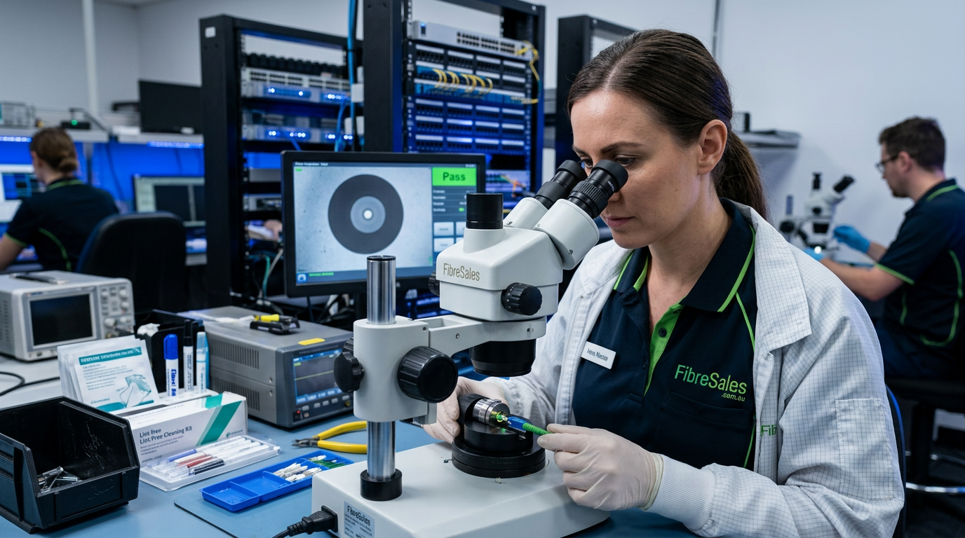
Connector interfaces are one of the highest contributors to unexpected attenuation increases.
Typical symptoms:
- sudden drop in received optical power
- intermittent link degradation
- inconsistent OTDR readings
Decision logic:
If attenuation appears suddenly, connectors must be inspected and cleaned before any fibre replacement is considered. In most cases, contamination is the root cause.
Related guide:
https://fibresales.com.au/fibre-optic-cleaning/
https://fibresales.com.au/fibre-connector-troubleshooting-guide/
Fibre Optic Attenuation Troubleshooting Guide: Splice Loss and Installation Quality
Splices introduce small but cumulative losses across long fibre runs.
Common causes:
- poor fusion alignment
- contamination during splice preparation
- incorrect fibre cleave angle
- inadequate splice protection
Decision logic:
If loss is consistent across a known splice location, re-splicing is preferred over replacing entire cable sections due to localisation of fault.
Related guide:
https://fibresales.com.au/fibre-optic-splicing-installation-guide/
Fibre Optic Attenuation Troubleshooting Guide: Bend Radius and Mechanical Loss
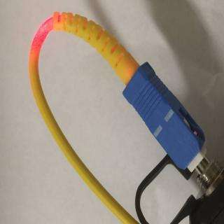
Mechanical stress causes micro-bending and macro-bending losses that are often overlooked.
Rmin≥10–20×DR_{min} \geq 10\text{–}20 \times D
Symptoms:
- gradual signal degradation over time
- performance variation when cables are moved
- inconsistent OTDR trace slope
Decision logic:
If attenuation changes with physical movement, routing and mechanical stress must be investigated before optical components are replaced.
Related guide:
https://fibresales.com.au/fibre-cable-routing-guide/
Fibre Optic Attenuation Troubleshooting Guide: Distance and Power Budget Limitations
Every fibre link operates within a defined optical power budget.
Pbudget=Ptx−PrxP_{budget} = P_{tx} – P_{rx}
Common causes of budget failure:
- excessive link distance
- too many connection points
- high-loss patch leads
- poor transceiver matching
Decision logic:
If all components test correctly but link still fails over distance, the issue is almost always power budget exhaustion rather than physical faults.
Fibre Optic Attenuation Troubleshooting Guide: OTDR Diagnosis of Loss Events
OTDR testing is used to locate where attenuation is introduced along the fibre path.
Common OTDR indicators:
- sudden loss spikes (connectors or splices)
- gradual slope loss (fibre degradation or bends)
- reflection peaks (poor connectors)
Decision logic:
OTDR results must always be validated after connector cleaning to avoid false loss readings caused by contamination.

Related guide:
https://fibresales.com.au/fibre-optic-testing-performance-guide-australia/
Fibre Optic Attenuation Troubleshooting Guide: Splice-Related Faults
Splicing issues typically occur during installation or maintenance activities rather than in stable networks.
Common causes:
- poor alignment during fusion splicing
- contamination during splice preparation
- inadequate splice protection
- incorrect fibre preparation length
Decision logic:
If OTDR traces show discrete loss events at known splice points, re-splicing is prioritised over full cable replacement. This is because splice faults are localised and isolated.
Related guide:
https://fibresales.com.au/fibre-optic-splicing-installation-guide/
Connector Fault Isolation
Connector faults are one of the most misdiagnosed issues in fibre networks.
Typical causes:
- poor mating alignment
- contamination on ferrule end faces
- worn connectors
- incorrect connector types or mismatches
Decision logic:
Connector faults are always isolated before fibre-level investigation. If multiple links fail across different segments, connectors become the highest probability failure point.
Related guide:
https://fibresales.com.au/fibre-connector-troubleshooting-guide/
Environmental and Installation Influences
External conditions significantly affect fibre performance over time.
Common environmental risks:
- vibration in industrial installations
- moisture ingress in outdoor systems
- rodent or mechanical damage
- poor enclosure sealing
Decision logic:
If faults appear gradually over time, environmental degradation is more likely than installation error. If faults appear immediately after installation, workmanship issues are more likely.
Related guide:
https://fibresales.com.au/armoured-fibre-cable-guide/
Structured Troubleshooting Sequence
Professional troubleshooting follows a strict hierarchy:
- Visual inspection
- Connector cleaning
- Continuity verification
- Insertion loss testing
- OTDR analysis
- Physical route inspection
- Component replacement only if required
This sequence is intentional. It prevents unnecessary replacement of fibre infrastructure when the fault is environmental or localised.
Engineering Decision Insight
Most fibre faults are resolved at the lowest-cost intervention point when correct decision logic is applied. In practice, cleaning resolves more issues than replacement, and inspection resolves more issues than testing.
Technicians prioritise:
- cleaning before replacement
- physical inspection before testing
- localised fault isolation before system-wide changes
This reduces unnecessary downtime and improves diagnostic accuracy.
For fibre optic testing equipment, cleaning tools, fusion splicers, and fibre infrastructure solutions, visit www.fibresales.com.au