Introduction
An Optical Time Domain Reflectometer (OTDR) is one of the most powerful diagnostic tools available for fibre optic testing. While many technicians focus on interpreting the OTDR trace, the event table often provides the quickest way to identify faults, excessive attenuation and poor installation practices.
Understanding how to read an OTDR event table allows installers and network engineers to pinpoint the exact location of connectors, fusion splices, reflections and fibre faults without unnecessary guesswork. Whether commissioning a new fibre network or troubleshooting an existing installation, accurate event table interpretation leads to faster fault isolation and more reliable network performance.
This guide explains how OTDR event tables work, what each measurement means, and how to use the information to make informed engineering decisions.
If you’re new to fibre testing, begin with our Fibre Optic Testing Performance Guide, which explains the complete testing process before examining reference methods in detail.
What Is an OTDR Event Table?
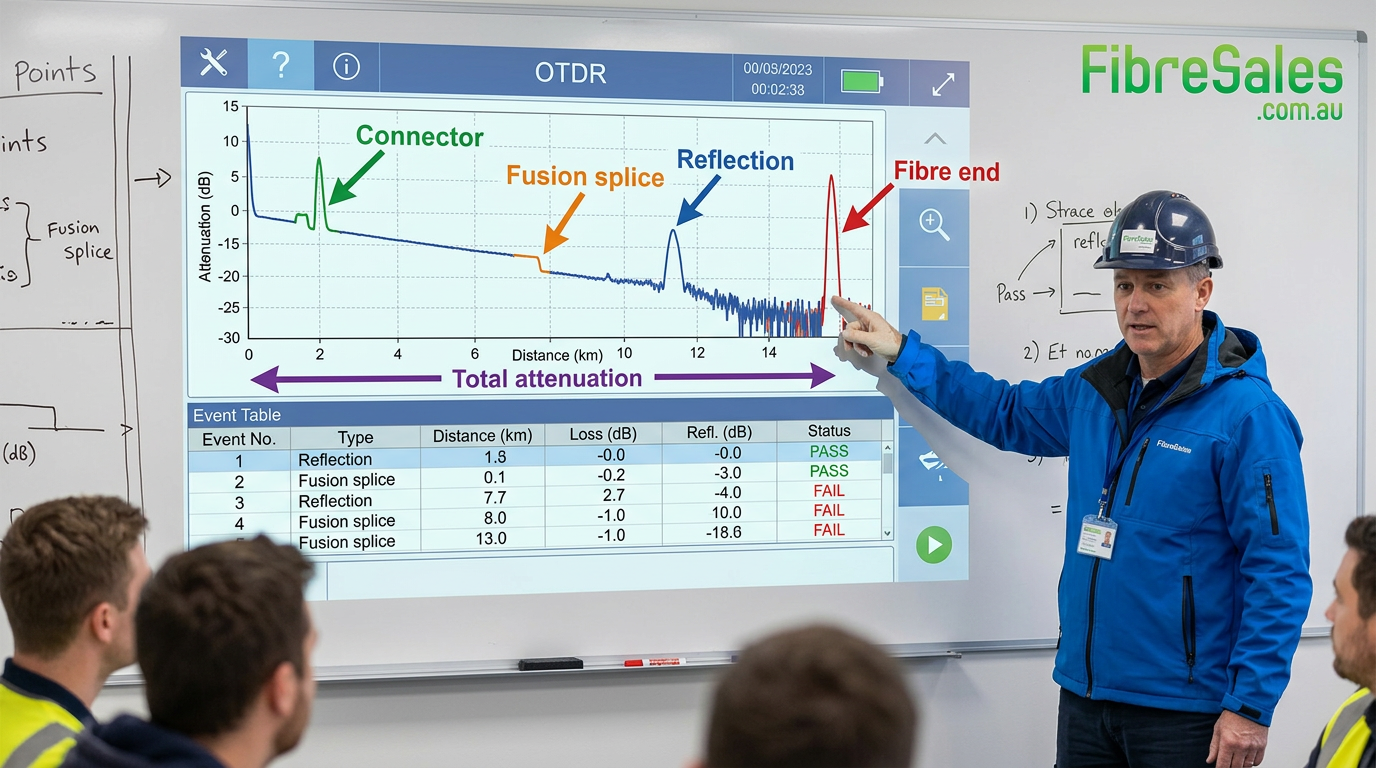
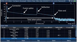
An OTDR event table is a detailed list of every significant event detected along a fibre optic link during testing. Each event represents a change in the optical path where light is reflected, absorbed or scattered.
Unlike the graphical trace, which provides a visual representation of the fibre, the event table converts the test into measurable data. This allows technicians to accurately determine the location and characteristics of every connector, splice and termination point.
Typical events include:
- Fibre connectors
- Fusion splices
- Mechanical splices
- Optical splitters
- Fibre ends
- Reflective faults
- High-loss sections
| Event | Appearance | Typical Loss – Typical Cause Recommended Action |
|---|---|---|
| Connector | Reflective | 0.2–0.5 dB Dirty or Damaged Inspect and clean |
| Fusion Splice | Non-reflective | 0.02–0.10 dB Poor cleave or alignment Re-splice |
| Mechanical Splice | Reflective | 0.2–0.5 dB Alignment issue Inspect or replace |
| Fibre End | Large reflective spike | N/A End of Fibre Verify end location |
| Macrobend | Gradual loss | Variable Tight Bend Radius Reroute Cable |
| Ghost Event | False reflection | N/A Multiple reflections Confirm with bi-di test |
OTDR Event Reference Table
Note: splice loss can vary because of backscatter differences (the “gainer” effect), testing from both ends provides a more accurate splice loss measurement
Engineering decision
If the event table identifies a single connector with significantly higher loss than neighbouring events, inspect and clean that connector before replacing the fibre cable or transceiver.
Understanding Every Column in an OTDR Event Table
Although layouts vary between OTDR manufacturers, most event tables contain the same core measurements.
| Event Table Column | What It Shows | Why It Matters |
|---|---|---|
| Event Number | Sequential event identifier | Helps reference individual events during troubleshooting |
| Distance | Location from the OTDR | Allows faults to be located accurately in the field |
| Event Type | Connector, splice or reflection | Identifies the physical component |
| Event Loss (dB) | Optical loss at the event | Indicates installation quality |
| Reflectance (dB) | Amount of reflected light | Useful for connector assessment |
| Total Loss (dB) | Accumulated attenuation | Confirms overall link performance |
Technicians should always evaluate the complete event table rather than relying on a single measurement.
OTDR Event Types Explained
Every event tells a different story about the condition of the fibre network.
Connector Events
Connector events usually generate both insertion loss and optical reflection because two polished fibre end faces meet inside the connector.
Higher-than-expected connector loss may indicate:
- Dirty ferrules
- Damaged connectors
- Incorrect polishing
- Poor connector mating
Fusion Splice Events
Fusion splices normally appear as non-reflective events with very low insertion loss.
A quality fusion splice typically produces minimal attenuation and little or no measurable reflection.
Mechanical Splice Events
Mechanical splices generally produce more loss and greater reflectance than fusion splices due to the physical alignment method.
Fibre End Events
The final event normally displays a large reflection because light exits the end of the fibre.
Ghost Events
Ghost events are false reflections created by multiple internal reflections. They do not represent actual fibre components and should always be verified before repairs are undertaken.
Engineering decision
Never replace a connector solely because it appears as a reflective event. Confirm the reflectance level, insertion loss and physical condition before taking corrective action.
Understanding Insertion Loss
Insertion loss measures how much optical power is lost as light passes through an event.
Higher insertion loss may result from:
- Dirty connectors
- Poor polishing
- Fibre misalignment
- Damaged ferrules
- Poor quality fusion splices
The OTDR event table allows technicians to identify exactly which event contributes the greatest optical loss.
Engineering decision
If one connector contributes most of the link attenuation, replacing or cleaning that connector is often more effective than replacing the entire fibre link.
Understanding Reflectance
Reflectance measures how much light is reflected back towards the OTDR.
High reflectance can reduce network performance and affect high-speed optical transmission.
Common causes include:
- Dirty connectors
- UPC connectors where APC connectors are required
- Air gaps
- Damaged ferrules
- Poor polishing
Maintaining low reflectance is particularly important for long-distance singlemode networks.
How Engineers Analyse an OTDR Event Table
Professional fibre technicians rarely begin with the trace. Instead, they follow a structured process.
- Check total link attenuation.
- Review cumulative loss.
- Locate the highest-loss event.
- Compare measured loss with design expectations.
- Inspect connectors before replacing hardware.
- Verify fusion splice quality.
- Repeat testing after corrective action.
This structured approach reduces unnecessary maintenance and improves troubleshooting accuracy.
Common OTDR Event Table Mistakes
Many incorrect diagnoses occur because the event table is misunderstood.
Common mistakes include:
- Confusing reflectance with insertion loss
- Ignoring launch lead requirements
- Misinterpreting ghost events
- Testing at an incorrect wavelength
- Using insufficient averaging time
- Failing to compare results against baseline measurements
Engineering decision
If the first event appears abnormal, verify the launch lead before investigating the installed fibre network.
OTDR Best Practices
To obtain reliable event table results:
- Clean every connector before testing.
- Use both launch and receive fibres.
- Test at the correct operating wavelength.
- Allow sufficient averaging time.
- Compare results with previous test records.
- Record all test reports for future maintenance.
Consistent testing procedures improve long-term network reliability and simplify future fault finding.
Engineering Decision Insight
An OTDR event table provides a detailed map of the optical network. Rather than simply identifying where a fault occurs, it helps determine why the fault exists and which corrective action is most appropriate.
Experienced technicians use event tables to guide inspection, cleaning and repair decisions before replacing expensive network components. Understanding the relationship between insertion loss, reflectance and cumulative attenuation is fundamental to maintaining reliable fibre optic infrastructure.
For professional OTDRs , Power Meters, Light Sources, Cleaning Products and Inspection Microscopes, visit www.fibresales.com.au to explore Australia’s growing resource centre for fibre optic products, technical guides and professional testing solutions.